Technical Resources
Everything You Need to Know – Resources from Data, Video, and Fiber Optics
Welcome to The SCOOP, an exclusive in-house publication solely focused on bringing the electric cooperative, broadband, and manufacturing communities together with relevant information about products and issues impacting the market.
The Scoop Vol. 2 – An Exclusive Publication for Electric Cooperatives
Included in this issue:
View Now
Contractor Chronicles – An Exclusive Publication for Network Contractors

Included in this issue:
View Now
The Scoop Vol. 1 – An Exclusive Publication for Electric Cooperatives
Included in this issue:
- The Fiber Optic Dilemma
- Middle Mile and Grid Optimization Options
- Maximizing Your Network ROI
View Now
Read Our Most Recent Articles:
Quick Fact: Fiber Optic technology is one of the “greenest” out there. It takes a lot more energy to send a sustained electric signal than it does a single flash of light. In this day and age where consumption has to be kept to a minimum, lower energy output and consumption means a smaller carbon footprint on the environment.
Quick Fact: Because fiber optic cable transmits light, not electricity, they don’t degrade over time like wire cables. They’re not affected by water, wind, ice, or extreme heat! Though they’re not immune to damage, they can take a lot more abuse than wire cables. In the long run, this means less cost for both you and the consumer.
Click on the heading to expand the category:
4K Ultra HD vs. 1080p Full HD
What is 4K Ultra HD?
Simply put, 4K Ultra HD is just a higher resolution; roughly four times higher than regular 1080p Full HD
Think about it this way:
Many of you reading this page have High Definition (HD) TVs at home and you are pretty amazed at the picture quality. Unlike when we were young watching a ‘tube TV’, you can now see crisp clean photo-quality television like we never could have imagined!
Now, take that incredible 1080p HD picture with 2,073,600 pixels, and quadruple it to 4K Ultra HD with 8,294,400 pixels. The size of your TV hasn’t changed, but the pixels within that same TV have increased 4 times.
4K Ultra HD is a new class of high-definition resolution offering unprecedented picture clarity and detail. Although the technology is already in use in film production and movie theaters, it is just now coming to your home television, offering nearly 4,000 (or “4K”) pixels across the screen’s horizontal viewing area.
Before 4K Ultra HD arrived, the highest-definition resolution on the TV market was Full HD 1080p, which consisted of 1920 x 1080 pixels, thus giving it its “1080p” name. 4K Ultra HD has four times the number of pixels as Full HD (3840 x 2160 pixels, or 4096 x 2160 pixels for cinema screens), resulting in its “4K Ultra HD” title. The increased resolution made possible by 4K Ultra HD’s 8.3 million pixels (vs. Full HD’s 2.2 million) enhances picture quality by reducing gaps between pixels (called the “screen door” effect) and visible pixels. This sharpens detail and shows smoother lines so that even up-close images seem clearer, more realistic, and less pixilated.
 Besides enhancing your viewing experience, higher resolution 4K Ultra HD TVs also allow you to sit closer to a screen and/or view a larger screen without seeing pixilation of scenes. That’s why it’s possible for manufacturers to make larger TVs with screen sizes of 80 inches and above while still providing excellent picture quality. By enabling superior picture quality on large screens and enhanced picture quality even up close, 4K Ultra HD technology gives you more freedom in your home to sit wherever you like and watch on a larger screen without compromising clarity. All in all, the enhanced resolution in 4K Ultra HD products helps deliver a more detailed, immersive, and realistic entertainment experience.
Finding the Right HDMI Cable
Now that you know everthing that there is to know about 4K Ultra HD vs. 1080p HD, there is a lot to learn about connecting your cable TV recevier, streaming media player (Roku/Apple TV), DVD and your other devices to your TV.
In a nutshell, there are four HDMI cable types to choose from, each designed to meet a particular performance standard. Here is an overview of the HDMI cable types, their capabilities, and how to tell them apart. Look for these labels when choosing the HDMI cable that is best for your needs:
 |
Standard HDMI Cable – The Standard HDMI cable is designed to handle most home applications, and is tested to reliably transmit 1080i or 720p video |
 |
Standard HDMI Cable with Ethernet – This cable type offers the same baseline performance as the Standard HDMI Cable shown above, plus an additional, dedicated data channel, known as the HDMI Ethernet Channel, for device networking. |
 |
High Speed HDMI Cable – The High Speed HDMI cable is designed and tested to handle video resolutions of 1080p and beyond, including advanced display technologies such as 4K, 3D, and Deep Color. If you are using any of these technologies, or if you are connecting your 1080p display to a 1080p content source, such as a Blu-ray Disc player, this is the recommended cable. |
 |
High Speed HDMI Cable with Ethernet – This cable type offers the same baseline performance as the High Speed HDMI Cable shown above, plus an additional, dedicated data channel, known as the HDMI Ethernet Channel, for device networking. |
To learn more about HDMI Cables and how they compare, see our page dedicated to this subject: High Speed HDMI with Ethernet vs. High Speed HDMI
Multicom stock a large supply of High Speed HDMI Cables, both with and without Ethernet:
High Speed HDMI Cables:
MUL-HDMI-1.3-1.5M-MA-MA-HS-30 – V1.3 High Speed HDMI Cable, 1.5 Meter
MUL-HDMI-1.3-1.8M-MA-MA-HS-30 – V 1.3 High Speed HDMI Cable, 1.8 Meter
High Speed HDMI Cables with Ethernet:
MUL-HDMI-2.0-1.5M-MA-MA-HS-30 – v2.0 High Speed HDMI Cable, 1.5 Meter, with Ethernet
MUL-HDMI-1.4-1.5M-MA-MA-HS-30SC-A – V1.4 High Speed HDMI 1.4 Cable Ver. A, with Ethernet
HDMI Cables come in a wide assortment of configurations. Give us a call at 800-423-3594 – if we don’t have it in stock, we’ll make it for you.
Active vs. Passive CWDM and DWDM Systems - What's the Difference?
Both Coarse Wavelength Division Multiplexing (CWDM) and Dense Wavelength Division Multiplexing (DWDM) optical transport solutions are available as active or passive systems.
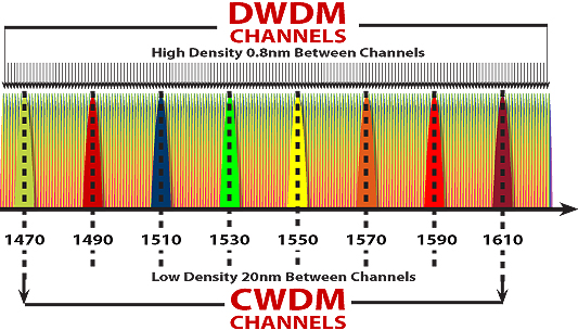
CWDMs utilize a channel spacing of 20nm, where a DWDMs utilize much denser spacing typically 0.8nm
Passive
In a passive (or non-powered) optical transport solution, either a CWDM or DWDM transceiver resides directly inside a device, such as a data switch or a router.
A typical example of this would be an IP switch that has a channelized SFP pluggable optic that is tuned to a specific CWDM or DWDM wavelength. The output from the channelized SFP transceiver connects to a corresponding passive multiplexer that combines and redistributes, or multiplexes and demultiplexes, the various wavelength signals.
As the channelized CWDM or DWDM pluggable SFP transceiver resides in the data switch or router, it means that the xWDM functionality is inherently embedded within the respective device.
Active
Active optical transport solutions have AC- or DC-powered components and are stand-alone systems separated from the devices that connect to them, such as data switches and routers.
A primary task of a stand-alone optical transport system is to take a short-range output signal and extend the reach of the signal while also converting it to a channelized CWDM or DWDM wavelength.
A typical example of Active DWDM Componentry:
An IP switch that has a 10Gb port populated with a ‘gray’ 1310 SFP+ optic, where the interface from the 1310 SFP+ port on the IP-switch is then cross-connected via a fiber jumper to the client interface port of a Transponder Card within an active optical transport system. A Transponder is a component that receives an incoming optical signal and then converts it to a channelized xWDM wavelength.
The active optical transport system then takes converted xWDM signals, combines them and transmits them with the help of some additional components, including passive multiplexers, and amplifiers if necessary, for long-haul applications. Due to the separation of the xWDM transport functionality from the endpoint device, such as a data switch or router, active optical transport systems also tend to be more complex than passive solutions.
Passive DWDM:
Active DWDM:
Advantages:
Disadvantages:
The Decision:
Whichever you decide on, Active or Passive DWDM, the selection is will be dependent on several factors:
- Distance requirements
- Network scalability
- Initial installation & future management
- Budget
- Technical ability
If there are no requirements for the distances and future network upgrades, the passive DWDM provides user-friendly and cost-effective solutions and is suitable for those with a tight budget.
If you have high bandwidth demands and are looking for a long-haul application with convenience when changing and making upgrades in the future, the active DWDM solution may be your best fit.
Are your fingers sore after installing “F” connectors on coax all day?
Did You Know that you could use a 7/16” nut driver (brown dot) and slip over the edge of the connector and push/slide the connector on? It is much easier on the finger tips and works well in the winter months!
ATSC vs. NTSC vs. QAM vs. DVB-T vs. ISDB-Tb - Understanding TV Signals
It’s complicated out there! Some of the technical language relating to purchasing a TV or TV tuner can seem difficult. It is common to see terms like ATSC, NTSC, and QAM being used, and it is important to understand what each term means and what the difference is between each of them.
But first, it is important to understand that TV signals are usually received in one of two ways, either by antenna or cable:
- The terms NTSC and ATSC relate to TV signals that are received over the air (known as OTA), using an antenna or aerial.
- QAM refers to TV signals that are received via cable.
And second, it’s also important to understand that the worldwide broadcasting formats are not standardized – different parts of the world use different formats which adds to the confusion and the abundance of letters – ATSC, NTSC, QAM… and many more.
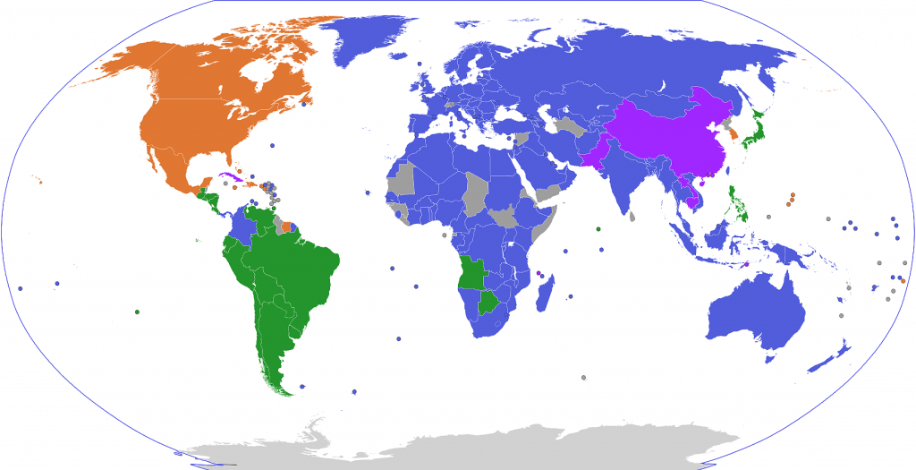
There are a lot of colors on this maps. The main ones to understand are:
| COLOR |
FORMAT |
|
Countries where ATSC and QAM are actively in use |
|
Countries where DVB-T/DVB-T2 are actively in use |
|
Countries where ISDB-T is actively in use |
| OTHER COLORS |
Other bizarre formats, or countries transitioning from one format to another |
 What is NTSC?
NTSC stands for the National Television System Committee, which were the group who introduced the original standards for analog TV transmission in the USA back back in the early 1940s. NTSC is generally used to refer to the old analog signal which was first adopted in the USA in the 1940s. It has largely been phased out in favor of digital ATSC broadcasting. NTSC is inferior to ATSC, as it is doesn’t deliver HDTV picture quality, or the widescreen format. Audio audio quality is also inferior.
As well as the USA and Canada, the NTSC system was or is used in Central America, the Caribbean, parts of South America, and in several Asian countries including Japan. High-power OTA NTSC broadcasting was switched off in 2009 in the USA, and in 2011 it was discontinued in Canada and most of the other countries.
 What is ATSC?
ATSC stands for the Advanced Television Systems Committee, which is the group that replaced the NTSC in the USA in 1982. ATSC is the OTA digital signal used in the USA. It is superior to the old NTSC analog system because it can deliver HDTV picture quality in a wide screen format, as well as being capable of providing theater quality audio.
To use an analog TV with ATSC you need a converter that is capable of handling the digital signal. The Federal Communication Commission (FCC) require that all new TVs have built-in ATSC tuners.
 What is QAM?
QAM stands for Quadrature Amplitude Modulation. QAM is essentially the cable version of ATSC, with QAM tuners allowing your TV to receive unencrypted digital signals from a cable provider (a cable box is required for the encrypted ones). In the cable television industry, QAM systems are used by Multi-System Operators (MSOs), and other network operators to deliver video, voice and data services. QAM systems are the mechanisms where signals are processed and distributed over a cable system and to be delivered to subscribers’ homes where set top boxes and cable modems convert the QAM signals back into useful voice, data and video.
This means that you generally will get free, usually local cable channels with a QAM tuner, but you will need a cable box or cable card to get the channels that are provided by the cable television providers.
 What is DVB-T?
DVB-T stands for Digital Video Broadcast – Terrestrial, and is the now the most common system used in Africa. Set-top boxes used by South Africa-based DSTV or Multi-Choice TV in a number of sub-Saharan African countries are based on this standard. Most (but not all) HDTV systems that are compliant with the ATSC standard are also compliant with the DVB-T standard.
 What is ISDB-T?
ISDB stands for Integrated Services Digital Broadcasting, and there are three types of ISDB – ISDB-S (satellite television), ISDB-T (terrestrial), ISDB-C (cable). All ISDB broadcasting is based on MPEG-2 or MPEG-4 standard for multiplexing with transport stream structure and video and audio coding (MPEG-2 or H.264), and are capable of high definition television (HDTV) and standard definition television
 Is there a Universal High Definition Encoder that works with all of these formats in all of these places?
Fortunately, there is. The Multicom MUL-HDENC-C-200 Single Channel Deluxe Digital Encoder Kit comes in the following options:
- MUL-HDENC-C-200-NA – Single Channel Deluxe HD Digital Encoder Kit, HDMI/Composite/Component Input, ATSC/J.83B QAM/DVB-T/ISDB-Tb output, CC, EAS, Default USA: QAM
- MUL-HDENC-C-200-MX – Single Channel Deluxe HD Digital Encoder Kit, HDMI/Composite/Component Input, ATSC/J.83B QAM/DVB-T/ISDB-Tb output, CC, EAS, Default MEXICO: ATSC
- MUL-HDENC-C-200-CO – Single Channel Deluxe HD Digital Encoder Kit, HDMI/Composite/Component Input, ATSC/J.83B QAM/DVB-T/ISDB-Tb output, CC, EAS, Default COLOMBIA: DVB-T
- MUL-HDENC-C-200-LA – Single Channel Deluxe HD Digital Encoder Kit, HDMI/Composite/Component Input, ATSC/J.83B QAM/DVB-T/ISDB-Tb output, CC, EAS, Default LATIN AMERICA: ISDB-T
Audio Video Cables
It’s always a bit frustrating to newcomers and seasoned audio-video enthusiasts alike when you’re faced with that array of input and output connectors. But it helps to understand which cables to use and what kind of signals each carries.
Below is a list of AV cables with an explanation of their capabilities. Multicom carries a wide array of AV cables – the ‘best buys’ are listed below each cable variation.
See more Multicom A/V Cables
DVI Cable
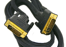 DVI (Digital Visual Interface) offers a high-bandwidth, digital-to-digital video connection that bypasses the digital-to-analog and analog-to-digital conversions necessary between components with only component video connections. Eliminating the undesirable artifacts of such conversions results in a more faithful reproduction of the original signal. DVI connections may optionally incorporate the High Definition Content Protection (HDCP) protocol, enabling them to pass copy-protected digital broadcast content (if this capability is present, it’s usually indicated by the designations “DVI-HDCP” or “DVI with HDCP”)
Steren 506-906 6 Ft. Single Link DVI-D Cable – 18 pin
Steren 506-956 6 Ft. Dual Link DVI-D Cable – 24 pin
HDMI Cable
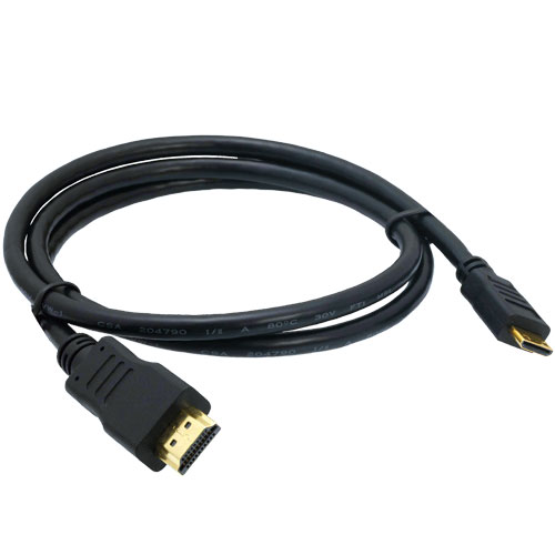 Essentially a more evolved version of DVI, HDMI (High-Definition Multimedia Interface) adds digital audio transmission to provide a convenient, one-cable solution to digital A/V connectivity. It offers significantly greater bandwidth than DVI, enabling it to transmit higher-definition uncompressed digital video signals, and establishes a platform for the transfer of future as well as current display formats. And it does all this using a single cable, with a smaller, sleeker connector than DVI. Unlike DVI, all HDMI connections are equipped with the High Definition Content Protection (HDCP) protocol, enabling them to pass copy-protected digital broadcast content.
There are two categories of HDMI cable: Standard (category 1) and High-Speed (category 2).
Standard (or category 1) cables have been tested to perform at speeds of 75Mhz, which is the equivalent of a 1080i signal. Therefore, a standard, category 1 cable is sufficient for HD televisions up to 1080i. But what about 1080p and higher? For that, you’ll want a high-speed, category 2 cable.
High-Speed (or category 2) cables have been tested to perform at speeds of 340Mhz, which is the highest bandwidth currently available over an HDMI cable and can successfully handle 1080p signals including those at increased color depths and/or increased refresh rates. High-Speed cables are also able to accommodate higher resolution displays, such as WQXGA cinema monitors (resolution of 2560 x 1600).
HDMI is backward-compatible with DVI, meaning that if your source component is equipped with a DVI connection and your display has HDMI (or vice-versa), you’ll be able to convert the video portion of the signal via an adapter, while maintaining the integrity of all-digital signal transfer. However, since DVI makes no provision for audio signals, you’ll need to establish separate audio connections when converting from either connection to the other.
Steren – 517-306BK- HDMI Jumper Cable, 6 FT
Component Video Cable
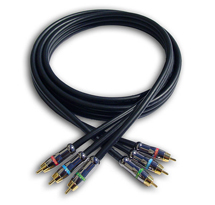 Though inferior to the digital connections listed above, component video is superior to both S-video and composite video because it provides improved color purity, superior color detail, and a reduction in color noise and NTSC artifacts. The 3-plug video output of a DVD player sends/receives the luminance (Y) and 2 color signals, each on a separate colored RCA cable.
Steren – 254-506IV – Component Video Cable, 6 foot
S-Video Cable
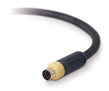 An S-video connection is much better than a composite video connection, but it is not as good as component video. This higher quality video input/output segregates chrominance (color) and luminance (light) signals for excellent reproduction from high-quality video sources such as S-VHS, Hi8 and DVD players.
ASKA CSVH-6 S-VIDEO PATCH CORD, 6’
J-SVIDEO-4 S VIDEO JUMPER, 4′
Optical Digital Audio Cable
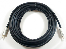 Making a digital connection (optical or coaxial) between your receiver and DVD player or CD player is a great option. A digital stream sends unprocessed sound information to your receiver (which, as a general rule, has a better digital-to-analog signal processor than a DVD or CD player) to be decoded and amplified. (In the case of SACD or DVD-Audio players, a 5.1-channel analog connection is necessary.) An optical digital connection sends signals in the form of light, as opposed to electrically. Optical cables have the advantage of being immune to EM and RF interference.
ASKA CTLK-6 OPTICAL TOSLINK AUDION CABLE, 6’
RCA Audio/Video Cable (Analog)
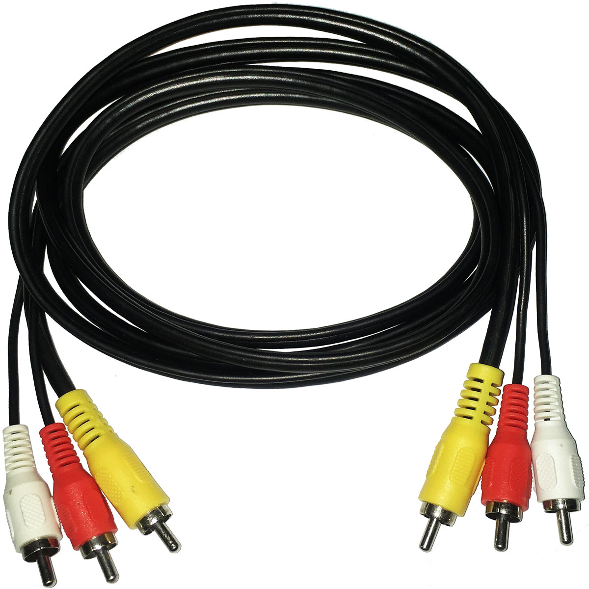 Stereo audio cables provide basic 2-channel analog audio connectivity between your VCR, CD player or DVD player and your home theater receiver (or the audio inputs on your stereo TV, in the case of your DVD player or VCR, if you don’t have a receiver). They provide a better signal transfer than coaxial RF A/V connections, but a digital connection is vastly superior.
Note: 3 pairs of high-quality stereo audio cables can also be used to connect high-resolution multichannel audio players (SACD or DVD-Audio) to 5.1-channel inputs provided for this purpose on certain receivers.
ASKA CRR-6B DUAL RCA STEREO CABLE, 6’
ASKA – CSD-6B – RCA Jumper, 6 FT
PICO MACOM JRR-6 RCA to RCA AUDIO VIDEO CABLE, 6′
Coaxial A/V Cable/Patchcords
 Coaxial A/V cable (also know as RF cable) connects your cable box or digital satellite box to your TV. It can also be used to connect a VCR to your TV (but composite or better A/V cables are preferable). If your TV only has coaxial RF inputs, you can use a video switcher and RF modulator to hook up advanced sources like DVD players or home gaming systems (but picture and sound quality is not nearly as good as with composite, S-video or component video connections).
Multicom has a wide variety of Coax Cable Jumpers ranging from 1 to 100 feet in length – at unbeatable prices! We will also make custom lengths for your specific application.
Cat5/6 Cable
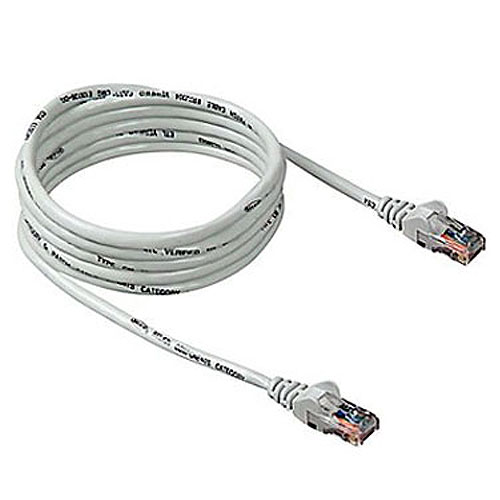 Category 5, 5e and 6 cables are high-speed data cables used for Internet connections and home networking, specifically with IP (Internet Protocol)-based home networks. Category 5 (or Cat 5) has a bandwidth of 100 MHz for networks up to 100 Mbps, and Cat 6 has 200 MHz and is recommended for Gigabit Ethernet (1,000 Mbps). Cat 5e is an enhanced version of Category 5. They require an Ethernet jack (RJ-45).
IEEE1394 – Firewire Cable
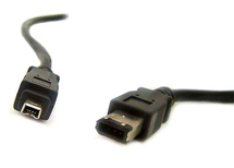 IEEE1394 (or FireWire or i.LINK) is a flexible digital connection that can pass HDTV signals using MPEG2 video to devices such as high-definition D-VHS recorders. It also supports daisy-chaining.
See more Multicom A/V Cables
Both Detroit and Cleveland claim to be the home of the first traffic light
We do know that both cities installed traffic lights in 1920, apparently independently of each other, and both inspired by the red, yellow, and green safety-light combo used by railroads.
The development and production of traffic equipment is the cornerstone of McCain. With 24 years of experience manufacturing traffic equipment, McCain is a recognized leader in the transportation industry. McCain offers a complete line of standard and customizable transportation equipment, including traffic controller cabinets, traffic controllers, signs, traffic signals, local controller software, and more.
By the way, do you know what ESPN stands for?

It doesn’t stand for anything.
But the story is, when ESPN started in 1979, they called themselves the Entertainment and Sports Programming Network (thus, ESPN).
However, the full name was dropped in February, 1985, when the company adopted a new corporate name – ESPN, Inc. – and a new logo. Based in Bristol, CT., 80 percent of ESPN is owned by ABC, Inc., which is an indirect subsidiary of The Walt Disney Company. The Hearst Corporation holds the remaining 20 percent interest in ESPN.
While you’re here…
 Multicom’s New Fiber Optic and Network Products are Leading the Way
‘Cost-Effective Quality’ is the buzz-word these days and this is what Multicom’s new line of fiber optic products deliver.
For a comprehensive look at all of our fiber optic, CATV and network offerings:
See our New Product Catalog
Cable Jacket Materials - What's Right for You?
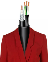
The cable jacket is the first line of moisture, mechanical, flame and chemical defense for a cable. More specifically, the jacket provides protection for the shielding and conductors within the cable. The jacket protects the cable from mechanical damage during and after installation. Cable jackets are not intended to replace internior cable reinforced armors, but they can provide a fairly high level yet limited means of protection. In addition, cable jackets also provide moisture, chemical, UV and ozone protection.
In most exterior applications, a physically robust cable jacket is needed because the environment may be harsh – either above or below ground – most cables are designed with this in mind. As always, there are varying levels of ruggedness available in the market, and you often get what you pay for.
Common cable jacket characteristics to consider when choosing an the cable that’s right for you are listed below:
| Cable Jacket Characteristic |
Benefit of Characteristic |
| Flexibility |
Ease of use and long-term flex life |
| Chemical resistance |
Life expectancy during exposure to chemicals |
| Low-temperature flexibility |
Suitability for arctic or winter climates |
| High-temperature survivability |
Determines peak and ambient operating temperature and contributes to ampacity rating |
| Color |
Identification, safety and appearance |
| Surface texture |
Ease of handling and installation |
| Elastic memory |
Flexibility and handling, especial in coil cords |
| Approvals/Compliance |
Suitability for a given application/jurisdiction |
| Flame resistance |
Safety and flame spread |
Types of Cable Jackets
There are many types of cable jackets available. It’s important to consider the jacket type when selecting the compatibility with the application’s connectors and environment. For example, an extremely cold environment may require cable jackets that remain flexible at very low temperatures.
The table below contains typical characteristics of some of the most common jacket types used both indoors and outdoors for most cables:
| Jacket Material |
Use / Benefit of Jacket Material |
PVC
(Polyvinylchloride) |
Polyvinylchloride can be formulated to function in a variety of environments and applications. It is usually low-cost, flexible, fairly rugged, and a flame/oil-resistant material. PVC can be made in either a matte,glossy or slick finish. IMSA 19-1 has a PVC jacket |
PE
(Polyethylene)
|
Excellent electrical properties with very high insulation resistance. Polyethylene can be stiff and very hard, however low density PE (LDPE) is more flexible. Moisture resistance is excellent. Properly formulated PE has excellent weather resistance. IMSA 20-1 has a PE jacket. |
PUR
(Polyurethane) |
Polyurethane is very elastic, with a very high memory, which makes it ideal for coil cord applications. It is abrasion resistant, has excellent flexibility in low-temperature environments, and performs well when exposed to oil and ozone. |
TPR/TPE
(Thermoplastic rubber/elastomer) |
Thermoplastic elastomers have excellent low-temperature properties without spending the money needed for a thermoset material. It has good chemical and oil resistance and is also quite flexible. Good abrasion resistance and surface texture, but is not as rugged as PUR. |
Thermoplastic CPE
(Chlorinated Polyethylene) |
Generally used in very harsh environments. It is lightweight, very rigid, and has a mildly rough surface texture and a low coefficient of friction. It is low-cost relative to the level of oil, moisture, chemical and UV resistance provided. |
Thermoset Polyolefins
(CPE, CSPE, etc.) |
The only products in this list that are truly melt resistant and in the same family of materials as natural rubber. They are highly elastic with excellent memory. This material is known of its ruggedness, low-temperature flexibility, UV stability and heat resistance. |
Multicom manufactures and stocks a wide range of cable for every application. We will custom-cut at no extra charge, you can use Multicom facilities as your warehouse – and if we don’t have the exact cable you need, we’ll make it for you to your specifications:
If you have any questions, please don’t hesitate to call us at 800-423-2594. We’re here for you.
Cat5 vs Cat6 Cable
Unshielded Twisted Pair (UTP) cable is by far the most popular cable around the world. UTP cable is used not only for networking but also for the traditional telephone (CAT1). There are more than six different types of UTP categories and, depending on what you want to achieve, you would need the appropriate type of cable. CAT5E is the most popular UTP cable, it came to replace the well known coaxial cable which was not able to keep up with the continuous growth for faster and more reliable tele and data communication networks.
| What is the difference between the popular CAT5E communications cable and CAT6? |
| Category 5 – CAT5 |
| Category 5 transmits at 100MHz frequencies, providing a rated line speed of up to 100Mbit/s and a max cable segment length of 100 meters. Most Category 5 cables, designed for early networks, only used two twisted pairs. Older Category 5 cables continue to make up the bulk of the world’s network infrastructure. |
| Category 5E – CAT5E |
| An improved specification to Category 5 was later introduced. By reducing noise and signal interference, CAT5E was capable of increasing rated transfer speeds to 350 Mbit/s over 100 meters. The new standard also required all cables to include four twisted pairs (all eight contacts). An optimized encoding scheme allows up to 50-meter lengths of CAT5E cable to perform at, or near, Gigabit Ethernet (1000BASE-T) speeds. |
| Category 6 – CAT6 |
| The mainstream adoption of Gigabit Ethernet (1000BASE-T) required new industry-standard cables capable of transmitting at a higher frequency of 250 MHz. Category 6 cable uses thicker-gauge wire, increased shielding, and more pair twists per inch to reduce signal noise and interference. The tighter specifications guarantee that 100-meter runs of Category 6 are capable of 1000 Mbit/s transfer speeds. 10-Gigabit Ethernet speeds are achievable when reducing cable lengths to less than 50 meters. |
| Category 6E – CAT6E |
| Category 6 Enhanced (6E) is an augmented specification designed to double transmission frequency to 500 MHz. By wrapping CAT6E in grounded foil shielding, full 10-Gigabit Ethernet speeds can be reached without sacrificing the max cable length of 100 meters. |
|
Details of all Communication Cables Categories:
| Name |
Typical Construction* |
Bandwidth |
Applications |
| Level 1 |
|
0.4 MHz |
Telephone and modem lines |
| Level 2 |
|
4 MHz |
Older terminal systems, e.g. IBM 3270 |
| CAT3 |
UTP |
16 MHz |
10BASE-T and 100BASE-T4 Ethernet |
| CAT4 |
UTP |
20 MHz |
16 Mbit/s Token Ring |
| CAT5 |
UTP |
100 MHz |
100BASE-TX & 1000BASE-T Ethernet |
| CAT5 |
UTP |
100 MHz |
100BASE-TX & 1000BASE-T Ethernet |
| CAT6 |
UTP |
250 MHz |
10GBASE-T Ethernet |
| CAT6A |
U/FTP, F/UTP |
500 MHz |
10GBASE-T Ethernet |
| CAT7 |
F/FTP, S/FTP |
600 MHz |
Telephone, CCTV, 1000BASE-TX in the same cable, 10GBASE-T Ethernet |
| CAT7A |
F/FTP, S/FTP |
1000 MHz |
Telephone, CATV, 1000BASE-TX in the same cable, 10GBASE-T Ethernet |
| CAT8.1 |
F/UTP |
1600-2000 MHz |
Telephone, CATV, 1000BASE-TX in the same cable, 40GBASE-T Ethernet |
| CAT8.2 |
F/FTP, S/FTP |
1600-2000 MHz |
Telephone, CATV, 1000BASE-TX in the same cable, 40GBASE-T Ethernet |
*The code before the slash designates the shielding for the cable itself, while the code after the slash determines the shielding for the individual pairs:
U = Unshielded
F = Foil shielding
S = Braided shielding (outer layer only)
TP = Twisted Pair
FTP = Foiled Twisted Pair
| What is the difference between the Shielded and Unshielded Twisted Pair? |
Shielded Twister Pair (STP) cables have additional shielding material that is used to reduce external interference. The shield also reduces the emission at any point in the path of the cable. UTP cables provide much less protection against such interference and the performance is often degraded when interferences or disturbances are present. Both types of cables, however, have some protection to interference due to the twisted pair design of the conductors.
The drawback of STP cable is that it will increase the total cost of an installation. STP cables are more expensive due to the shielding, which is an additional material that goes into every foot of the cable. The shielding also makes the cable heavier and stiffer. Thus, it is more difficult to handle.
| Why the ‘twist’ in twisted pair? |
Twisted pair are twisted together for the purposes of canceling out electromagnetic interference (EMI) from external sources; for instance, electromagnetic radiation from unshielded twisted pair (UTP) cables, and crosstalk between neighboring pairs. The advantage of twisting is that all wires are equally affected by external influences, so the unwanted signals are canceled out. The role of twisting is to minimize the interferences from external magnetic fields.
| The Features and Benefits of CAT5E and CAT6 Communications Cable: |
CAT5E Ethernet Cable
-
Category-5E Unshielded Twisted Pair (UTP) Cable
-
High-Performance Data Communications Cable
-
Suitable for 350MHz High-Speed Data Applications
-
Suitable for Gigabit Ethernet, Fast Ethernet and 155Mbps TP-PMD/CDDI
-
4-Pair – Easily Identified Color-Striped Pairs
-
AWG24 Solid Annealed Bare Copper Conductors
-
Excellent Attenuation and Crosstalk Characteristics
-
Nominal Impedance 100Ω±15%
-
DC Resistance <9.38Ω/1000ft
-
Mutual Capacitance <0.9pF/ft @ 1 kHz
-
Flame Retardant – Type CM CMG, CMH
-
Suitable for Indoor Installations
-
Exceeds EIA/TIA 568, UL, CSA and ISO/IEC 11801 specifications
-
UL/cUL or ETL Listed
- Supplied in 1000´ Pull Boxes or Reel in a Box
CAT6 Ethernet Cable
- Category-6 Unshielded Twisted Pair (UTP) Cable
Ultra-High-Performance Data Communications Cable
- Suitable for 550MHz High-Speed Applications, Critical Network Applications, Gigabit Ethernet, Fast Ethernet, Broadband Audio and Video, 155Mbps ATM, and 100Mbps TP-PMD/CDDI,NEXT, ELFEXT and RL Bandwidth Compliant
- 4-Pair – Easily Identified Color-Striped Pairs
- PE pair separator minimizes pair motion
- AWG23 Solid Annealed Copper Conductors
- 100% Tested Wiring Sequence and Continuity
- Excellent Attenuation and Crosstalk Characteristics
- Impedance 100?±15% – DC Resistance 23?/1000´
- Mutual Capacitance 14pF/ft Maximum @ 1kHz
- Velocity of Propagation 68%
- Flame Retardant – Type CM CMH, CMR
- Suitable for Indoor Installations
- Exceeds Category-6 ANSI/TIA/EIA 568B.2-1 and ISO/IEC 11801 standards and all proposed Category-6 requirements for high-speed, full duplex, parallel transmission protocols
- UL/cUL 1685, CSA, ETL Listed
- Supplied in 1000´ Pull Boxes or Reel in a Box
View Our Ethernet Cables
Coarse Wave vs. Dense Wave Division Multiplexing - What's the Difference?
First off, what is Wave Division Multiplexing?
Wave Division Multiplexing, better known as ‘WDM‘, is a method of combining or separating multiple wavelengths of light in or out of a single strand of fiber with each wavelength of light carrying a different signal, like a voice signal, video signal and/or data signal. The use of optical filters allows a certain range of wavelengths and lets another range of wavelengths pass through. Using a WDM in your network is a cost effective way to increase the capacity of a network.
Without a WDM, a single fiber would be dedicated to each customer’s voice, video or data device from the headend, or originating source, to the end user. This would account for a lot of fiber and potentially a lot of extra expense.

Multiple fibers from the headend to the end user – that’s a lot of fiber!
The foundation of WDM lies in the ability to send different data types over fiber networks in the form of light. By allowing different light channels, each with a unique wavelength, to be sent simultaneously over an optical fiber network a single virtual fiber network is created. Instead of using multiple fibers for each and every service (as above), a single fiber can be shared for several services (as below).

The WDM gathers all data streams together to be transported simultaneously over a single fiber.
With a WDM, a single fiber is used from the headend, or originating source, to the end user. Within that single fiber are varying wavelengths that handle all of the voice, video and data usage.
There are two different types of WDMs:
- Coarse Wave Division Multiplexing or CWDM: CWDM is standardized to have 18 different wavelength channels with a spacing of 20 nanometers (nm) starting at 1270nm and ending at 1610nm. Most systems use the eight channels in the upper band (eight channels from 1470nm to 1610nm). The advantage of CWDM systems is that it is always possible to upgrade at a later point in time to limit the installation cost on day one. The wider channel spacing places less stringent requirements on the lasers, which allows use of less expensive lasers without temperature controllers.
- Dense Wave Division Multiplexing or DWDM: DWDM devices are mostly used in the core networks to extend over very long distances and where more wavelengths are required between sites. The 16-40 wavelength channels are distributed in the C-band from 1530nm to 1570nm. If required, DWDM can be “over-layed” on a CWDM infrastructure to increase capacity further. Multicom’s MUL-DWDM-RM-D-16C2136 is a good example of DWDM that multiplexes 16 Channels (CH21 to CH36) over one fiber.
Typically CWDM and DWDM have lower insertion losses compared to the use of optical splitters. This significantly increases the reach of the network from the central office. Moreover, every customer has an assigned wavelength(s), providing greater security and making eavesdropping difficult if not impossible.
One Fiber vs. Two Fibers
The upstream and downstream signals can be sent through the same fiber at different wavelengths or on two separate fibers. Most CWDM systems are built as two-fiber systems where one fiber is used for the upstream and the other fiber is used for the downstream. In that case, each customer has two separate fibers and one wavelength. If only one fiber is used, every customer will have two separate wavelengths.
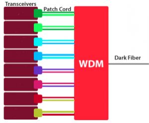
Bi-directional Transceivers used to transmit and receive data over a single fiber
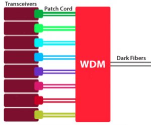
Fiber pair used to transmit and receive data on different fibers
Passive Optical Components can have a significant impact on the efficiency of communication network roll-outs. The incorporation of passive WDM devices reduces the amount of fibers in the network, decreasing both the footprint and investment cost of network roll-outs. In existing networks, these components allow capacity upgrades at a relatively low cost without additional construction works.
- Transceivers are wavelength-specific lasers that convert data signals to optical signals that can be transmitted into the fiber
- The Patch Cord or ‘Jumper’ connects the output of the transceiver to the input on the WDM
Component Video vs. Composite Video? What's the Difference?
There are an array of different connector types for audio visual equipment, but basically, they all fall into two camps: digital and analog.
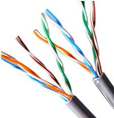
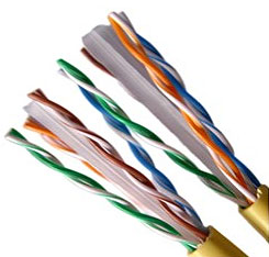
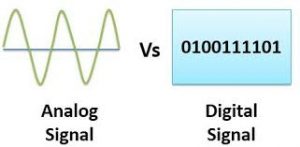 Older devices use analog signals, while newer ones use digital signals, and they each have different types of connectors to get everything to work together. In a home theater, analog signals usually use one of two different connector types: composite or component. Composite RCA cables feature one yellow connector for video, and red and white connectors for audio. Component cables use red and white audio connectors, but they divide the video into three components: one for luma (brightness) and two for color information. This is known as YPbPr component video.
Component and composite audio-visual connection cables both transmit video via an analog signal. But that’s where the similarities between the two formats end. Old-style composite cables are no longer supported by most devices. The newer component cable format was designed to work with modern high-definition devices. However, even component cables have had their day – high-resolution HDMI is now typically the connection of choice for the latest generation of audio-visual equipment.
Composite Video
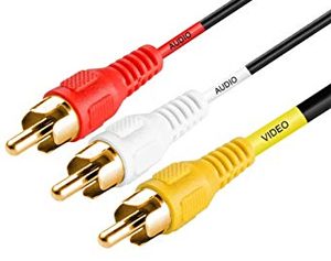
Composite Video Cable
A composite video cable — also known as an RCA or “yellow plug” cable — is an old standard that transfers a video signal through one cable and connector. It doesn’t support HD content or progressive scan images. Because the video signal is forced to travel through a single cable it is heavily compressed, losing much of its resolution and picture clarity. The cables also suffer from radio frequency interference, degrading picture quality.
Composite Uses
Composite video is a dying technology, because it can’t support HD video signals. When given the option, go for component over composite every time because this connection will always provide a better picture at higher resolutions. The only practical use for composite video today is when using older equipment, such as older video game systems or VCRs, which do not support the component video format. Because of this, some new HDTVs include at least one composite video input to make them compatible with old equipment.
Component Video
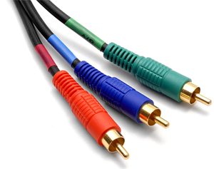
Component Video Cable
Component video splits the video signals into three cables — green, blue and red — with each transmitting a specific component of the video signal. The green cable (also called Y) transmits the brightness information of the signal. The blue and red cables (called Pb and Pr, respectively) transmit the blue and red components of the picture’s color. Green components are inferred by a combination of all three signals. Since component video is spread across three separate cables, it does not need to be as compressed as composite video, allowing support for HD resolutions as high as 1080, as well as progressive scan images that create smoother images with more defined edges.
Component Uses
Component cables initially replaced composite as the de facto analog video cable, thanks to its improved picture quality and HD support. Nearly all HDTVs made today have at least one set of component inputs. Component video is also supported by most video game consoles, DVD players, digital video recorders, cable set-top boxes and Blu-ray players.
Component Limitations
Component video cables are analog, just like composite cables. And also like composite cables they have inherent limitations that are tied to the analog format. Analog cables transmit their signals via waveforms, digital cables transmit their signals the same way a computer transmits data — through binary code that is decoded by the display device into a viewable picture. Because they travel via waveform, analog signals are susceptible to interference from radio waves and other electronic signals from nearby equipment. Analog signals also have less bandwidth than digital signals, which means increased compression that can negatively affect picture quality. Although less noticeable with component than composite, signals transmitted via component cable will not be as clear as signals transmitted digitally via cables like HDMI and DVI.
Most HDTVs use HDMI (High Definition Multimedia Interface) connectors, which use digital signals. Digital signals give you better sound, higher resolutions, and better color than analog signals.
Multicom stocks the highest quality HDMI 2.0 cables you can buy, at a fraction of what you’ll find in a retail store. Currently our MUL-HDMI-2.0-1.8M-MA-MA-HS-30 – High Speed HDMI 2.0 Cable with Ethernet – is on sale on our Online Store for $1.15 each (with FREE SHIPPING)!
- Supports full-resolution 4K, Adobe RGB Color, Deep Color, 3D, sYCC601 Color, and Adobe YCC601 to accurately display natural, vivid colors
- Supports Dolby Digital, DTS, Dolby True HD, DTS-HD MasterAudio, Audio Return Channel, and Lip Sync to deliver the highest quality and duplication of sound
- Compatible with the lossless compressed digital audio formats
More from Multicom’s Technical Resources:
Summary
While regular television signals, VHS tapes, and laserdiscs all encode visual data using lesser-quality composite video, DVDs use component video for encoding visual data. A DVD player with component video outputs, connected to a television with comparable inputs, will provide a picture far superior than one using composite video connections. Component video is also a step up from S-Video in that it is a multi-scan technology, which means it can deliver the video stream in differing modes to accommodate various frame rates for progressive-scan or interlaced televisions.
Component video cables are available in different configurations. All three cables might be encased in a single sheath with triple tails at each end, or the cables might be bonded or ribboned together. Three single RCA or coaxial cables can also be used but should be the same length and type. Increased cable quality, tips, and shielding add to the cost, as will the length of the cables.
Many people have numerous free cables around the house from purchasing past equipment, and some people opt to use these to connect component video. Bear in mind that standard cables are color-coded red and white, so care must be taken to match the green, red, and blue jacks with the same wire on both pieces of equipment. Cabling made for component video is color-coded green, red, and blue for this reason. It is also usually of higher quality and might have better shielding coverage and lower impedance levels. If results are unsatisfactory using standard cables, a cable upgrade might make a difference.
Contractor Chronicles - 5 Components for Fast and Accurate Locates

Accurately locating buried utilities will help prevent costly damages as well as prevent the needless hassle. These five components can help ensure the locate is done accurately and efficiently.
1. The Wire
Using an extra high-strength copper-clad steel tracer wire can provide locators with an accurate read on the location and depth of the buried cable. Wire with a high carbon steel core, metallurgically bonded with a copper cladding, that is uniform and continuous, creates a bi-metal conductor that acts as one and is corrosion resistant.
Not only are these systems easy to install and necessary for accurate underground pipe detection, but they are also:
- Corrosion, moisture, chemical, oil, impact, crush, and abrasion-resistant
- Carry a much lower theft value than copper wiring systems
- Comes in sizes ranging from 14 through 6 AWG
- When grounded with a magnesium ground rod, corrosion is redirected to the ground rod, thus preserving the integrity of your tracer wire system
- Depending on the type of tracer wire you use, the break strength FAR exceeds typical copper applications:
- HF-CCS (High Flex)- 43% higher in strength than copper tracer wire
- HS-CCS (High Strength)- 227% the break load of copper tracer wire
- HDD-CCS (Directional Drilling)- 700% the break load of copper
- Considerably lower in cost and excellent price stability compared to copper counterpart
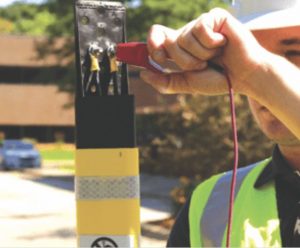 2. Test Station
Test station marker posts are essentially a two-for-one: they provide easy access to tracer wire for locate technicians, as well as provide a highly visible and effective warning message to potential excavators.
Oftentimes, tracer wire is poorly maintained or exposed to the elements. An above-ground test station like the Rhino TriView™ Test Station and its friction-fit cap protects both the tracer wire and access terminals from severe weather and vandalism.
In areas where upright marker posts are not practical, the Rhino HideOut™ Test Station is an ideal choice. The flush-mounted test station can be mowed over while still providing a visible warning. It has a telescoping terminal board for quick access to the tracer wire.
3. Hardware
Locating multiple utility lines can become a tedious task for the locator – having to locate lines separately and continuously reconnect to the different terminals.
Innovative hardware like the Iso-Switch, can significantly speed up the locating process as it allows the locator to connect to all the facilities at once.
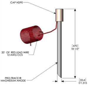 4. Ground
Grounding anodes should be installed at all dead ends of the tracer wire system to complete the electrical circuit needed to enhance the signal for locating purposes. Grounded tracer wire allows for the locator to use a lower frequency which provides the most accurate results for locating. Higher frequency has a tendency to bleed-over into other buried utilities, making the locate inaccurate.
The best way to ground a tracer wire system is to install a 1.5 lb. drive-in magnesium ground rod and an access point at each tracer wire dead end. An access point will protect the wire and provide a direct connection point for a utility locate transmitter to connect to the tracer wire. It also provides a connection point for the ground rod wire and allows the ground connection to be turned on and off, allowing you to control the signal on the target line.
5. Connectors
A tracer wire system is only as good as its weakest connection. Connectors with superior strength that are water and corrosion-proof protect vulnerable wire splices and keep the locate signal flowing across connections.
Using cheap alternatives like electrical tape will result in corrosion. A corroded connection point can cause the locate signal to stop at the connection point, making the rest of the buried utility unlocatable, which could end in disaster for the excavator.
This article was kindly contributed by Trident Solutions. We’ve brought together the distribution and manufacturing communities to publish
“The Contractor Chronicles”, a new publication focused on network contractors and operators. The inaugural issue includes the five things you need to know before installing cable or learn from some of our leading partners on service delivery, the FTTH ecosystem, fusion splicing, and power meters.
Contractor Chronicles - 5 Project Details to Know Before You Start Installing Cable

Because every duct run is unique, every project you take on will be unique. So no matter if you’re on your first cable installation project or your five hundredth, we believe there are five details you need to know before you get on the job site to start installing cable.
Why? Knowing this information will set you and your crew up to work the most efficiently and effectively, ultimately maximizing your time, safety, and profit. Here they are:
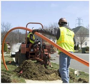 1. Fiber OD
The OD (outer diameter) of your fiber is important on so many levels. The first question it helps calculate is: What is your duct fill ratio? For best blowing performance, your fill ratio should not exceed 60%. Secondly, this detail informs what equipment (i.e., blower, cable packs, etc.) you’ll need to execute the install successfully. Note that we did not say “fiber count”. This is because the OD (outer diameter) varies by manufacturer; while your fiber count from Manufacturer A matches one from Manufacturer B, the fiber OD may not match.
2. Duct OD / ID + Type of Duct
Similarly, the outer diameter (OD), inner diameter (ID), and type of duct you’re installing into completes your fill ratio calculation above and indicate which duct packs you’ll need to connect your fiber blower to the conduit. As an example, if your fiber OD is 1″ and you’re installing into a 2″ duct, the Condux Gulfstream™ 400 fiber blower is the best suited for the job at hand, along with the right sized Cable and Duct Packs.
3. Length of Run + Hand-Hole-to-Hand-Hole Distances
Starting with the big picture in mind helps create efficiencies as you tackle the whole project, one run at a time. The total length of your run plus the hand hole locations help you identify where the best and safest locations are for loops, where couplers are needed to bridge the gap, and potentially also where the best starting point may be. Without knowing where you’re going, it’s more difficult to get started with your best foot forward.
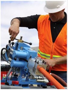 4. Locations of 90s + Loops
The more information you know about your pathway, the more you can plan, and the better equipped you’ll be. Piggybacking off of #3, knowing how many 90s and loops you’ll encounter, will help you devise a plan that is safe and efficient, and you’ll know what tools and equipment you’ll need on hand to execute. For example, when doing a loop we suggest you connect ~15 feet of extra duct from the exit point to the new entry point with couplers to set up for a seamless install.
5. Compressor Size Needed
For most traditional duct and fiber we recommend a 375 cfm compressor, with 100 PSI – but your answers to #2 (duct details) and 3 (distance) above will help guide this recommendation as well. With all that being said, it is important here to point out that your blowing distance and performance is very dependent on the integrity of your duct. Bad duct equates to low performance (more on this in a minute).
While it is still possible to install cable without this information up front, we guarantee you will have better luck and a more productive install if you take the time to plan and prep accordingly. And, we’d be remiss if we didn’t take it a step further and make a final recommendation. When you get to the job site, with all tools and equipment in hand, always do a pressure test, a proofing test, and a crash test.
Why? One of the most important variables to know when installing fiber is the integrity of the duct. Each of these tests will give you insight into the integrity of the duct you’re installing into and what, if any, challenges you might encounter (or could avoid with additional pre-install work).
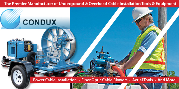
Multicom stocks a large variety of products by CONDUX International, the premier manufacturer of underground and overhead cable installation tools and equipment for the data/telecom and electric power markets. Learn More…
This article was kindly contributed by CONDUX. We’ve brought together the distribution and manufacturing communities to publish
“The Contractor Chronicles”, a new publication focused on network contractors and operators. The inaugural issue includes the five things you need to know before installing cable or learn from some of our leading partners on service delivery, the FTTH ecosystem, fusion splicing, and power meters.
Contractor Chronicles - Active Fusion Control and Other Automatic Low-loss Enabling Features of the 90S+ Fusion Splicer
 With the introduction of the 90S+, Fujikura has also introduced the new Active Fusion Control (AFC) technology to further improve the dependability and consistent performance of core alignment fusion splicers. With each generation of fusion splicer development, Fujikura has continued to innovate and improve the state of the art in fusion splicing, and AFC in the 90S+ is the latest example.
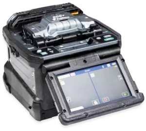
Fujikura 90S+ Fusion Splicer
Splicers incorporating the Profile Alignment System (PAS) core alignment system have long been recognized as providing the most consistent and reliably low-loss splicing results. AFC further enhances the consistency of splicing performance by providing a sophisticated algorithm to alter the splicing parameters to mitigate against increased loss due to a poorly cleaved fiber end.
A less-than-ideal cleaved fiber end may result in core deformation at the splice point (micro-bending) and therefore higher loss. AFC uses the cleave quality monitoring system to consider when the cleave quality is such that the fusion parameters should be altered to avoid an elevated splice loss. To avoid the higher loss, more fusion heating time or power is required to create greater diffusion in the fiber core and lessen loss due to micro-bending. It should be noted however that a PAS core alignment splicer generally employs a relatively short, two-second arc time to ensure ultraprecise core alignment. If the arc time or power is too great, the cladding of the two fibers will self-center due to the surface tension of the molten glass during the fusion arc, and core alignment will not be maintained unless the cores are already perfectly in the center of the cladding. Therefore, sophistication is required in the proprietary analysis and algorithms of AFC to ensure it is used to the best advantage.
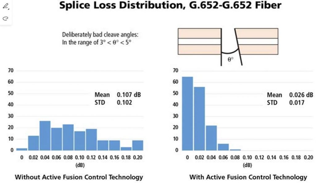
Splice loss results with poor cleave quality are shown with and without AFC. In this case, cleaves with angles in the range of 3° to 5º were deliberately created to illustrate the benefits of AFC.
The introduction of AFC in the 90S+ is only the latest in a series of innovations and features that Fujikura has introduced to ensure consistent low-loss splicing results with PAS core alignment fusion splicers. The previous Fujikura introduction of Active Blade Management technology was another such innovation and is still unmatched by any other fusion splicer manufacturer. Active Blade Management utilizes Bluetooth® communications between the splicer and CT50 cleaver to monitor cleaving performance and automatically rotate the cleaver blade when cleaving consistency begins to degrade. With the combination of Active Blade Management technology (to prevent poor cleaving results as much as possible) and now AFC (to prevent high loss when a poor cleave is encountered), the 90S+ Splicer provides near-perfect immunity to cleaving-related issues.
The automated opening and closing of both the wind protector and the splice sleeve heat shrink oven is another example of Fujikura innovation. This provides an obvious boost to splicing productivity since it frees up the operator to concentrate on fiber preparation, wrapping completed splices into the splice tray, etc. However, the benefits go far beyond improvements in splicing operational time. In a dusty splicing environment, the automation of the wind protector and heat shrink oven can also be utilized to minimize the risk of dust getting into the splicer V-grooves (which might result in unstable core alignment) and to avoid contamination issues with the splice sleeve heat shrink process. These capabilities are also exclusive Fujikura fusion splicer features.
In a core alignment splicer, as noted above, a controlled arc time at the correct arc power is essential in order to ensure consistent and precise core alignment. Fujikura previously introduced Auto Arc Calibration to monitor the brightness of the glowing fibers during the arc, and thereby self-correct and fine-tune the arc power splice-by-splice, making small adjustments to the arc power as the electrode condition changes. While we still recommend a manual Arc Calibration at the start of daily splicing activities (especially if there has been a change in weather), the Auto Arc Calibration can also compensate for changes in atmospheric pressure which could otherwise result in a stronger or weaker arc intensity.
Fujikura also previously introduced Automatic Fiber Discrimination which can use image analysis to identify the fiber type being spliced in order to automatically ensure that the proper splice mode and arc parameters are used for that category of fiber. This is very helpful when the operator has some uncertainty in fiber type, and it works in conjunction with Auto Arc Calibration to ensure proper arc conditions and heating of the fibers during splicing. It should be noted that all of these innovations function automatically and are therefore not dependent on operator habits or skill, or operator attention to routine maintenance guidelines.

Summary of Fujikura innovations
Fusion splicers using the Profile Alignment System (PAS) can align single-mode fiber cores to a sub-micron accuracy, eliminating core-clad eccentricity as an issue. Purchasing a core alignment splicer is a significant investment, and the end user has a justifiable expectation of the best and most reliable low-loss fusion splicing. The Fujikura 90S+ is the only splicer to offer all of the automated features above to ensure consistent and repeatable low-loss splicing performance.
This article was kindly contributed by AFL. We’ve brought together the distribution and manufacturing communities to publish
“The Contractor Chronicles”, a new publication focused on network contractors and operators. The inaugural issue includes the five things you need to know before installing cable or learn from some of our leading partners on service delivery, the FTTH ecosystem, fusion splicing, and power meters.
Contractor Chronicles - Leveraging the IoT for Damage Prevention

Most of the applications for the Internet of Things (IoT) are still in the incubation stage. Whether we want to solve challenges in modern medicine, make our cities easier to navigate, or increase the efficiency of our farmers, there’s still a long road ahead.
As network operators and those involved in the trade, the onus is on us to think about the latest products and tools that not only enable the technologies of the future, but also allow us to protect the vital infrastructure in ways we haven’t before.
There are three technologies I suggest network operators in the private and public sectors consider implementing to aid with damage prevention:
- Line Power to Remote Monitoring Devices
- Fiber Optic Acoustic Detection
- Remote Fiber Test Systems
None of these technologies are new, but recent developments further increase the value for service providers. Cloud-based visibility is one trait these systems have in common that truly allows for measurable reductions in operating expenses – the holy grail of cost-cutting.
Line Power for Monitoring
Until recently, delivering power and communications to a device more than 300 meters from the switch was a complicated and costly endeavor. Locating a device on someone’s property, such as a wireless access point or camera, usually meant you were trying to negotiate using power from their building or requesting a meter dropped from the utility nearby.
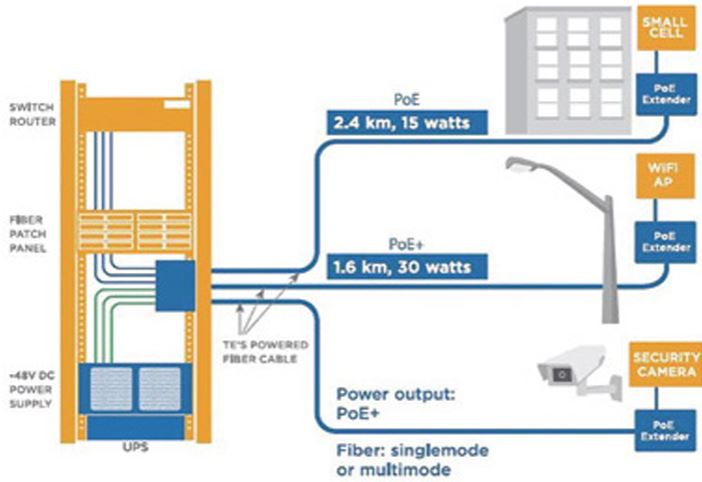
A new, powered fiber cable design featuring a pair of conductors flanking strands of fiber was developed in tandem with a system solution that is inexpensive and easy to deploy. This system uses Class II SELV power supplies that do not require a certified electrician to install. The compact cable design requires only one tool to strip and access the conductors and fiber. The powered fiber hybrid cable can be supported by traditional telephone “P-Clamps” or installed in a microduct pathway for reduced installation costs.
The power system is capable of balancing power between multiple devices that require different wattages. The distances you can reach with the system vary by the size of the conductor and the power required at the device, but it is possible to reach up to 3km from the power supply while 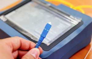 delivering 15 watts of power. This would accommodate a typical WiFi access point.
While airports, industrial sites, and campus environments already make use of the powered fiber solution, it could also be used by service providers to monitor critical facilities. Camera systems could be deployed using powered fiber around perimeters of secure data centers, earth stations or colocation facilities. Additional devices such as site access controllers or smart lighting could be run off the same shelf at distances beyond the current capabilities of PoE. All of the aforementioned devices are available to be accessed from the cloud, which could allow for reduced staffing requirements or truck rolls at those facilities.
Fiber Optic Acoustic Detection
A remarkable technology, Fiber Optic Acoustic Detection (FOAD) uses algorithms to decipher sound vibrations impacting a single optical fiber strand. The system is able to detect these sounds based on the backscatter of light pulses the vibrations create. This technology is capable of interpreting sounds created by someone walking by, passing trains or vehicles, gun shots, and more. Developers are constantly analyzing the backscatter modulations to further increase the system’s ability to interpret sounds.
FOAD systems detect sounds that are three meters from the fiber being monitored. The conditions of the cable as well as the type of pathway are two key factors that impact the ability of the system to operate optimally. Believe it or not, older optical fiber and cable designs are typically preferred, which makes using degraded fiber more attractive. These fibers may have been previously removed from service due to their degradation that limits their ability to support current capacity and data rates.
While the government and railroads are early adopters of this technology, network operators can certainly use it for their own security and analysis. Imagine that a backhoe pierces the soil near your cable, and your records don’t show a completed dig ticket for that location. The system might generate an alarm to notify your OSP manager via text message to further investigate the situation. Even if you can’t prevent the potential damage done to the cable, the ability to pinpoint the location practically eliminates the meantime-to understand (MTTU) a break in the fiber.
 Remote Fiber Test Systems
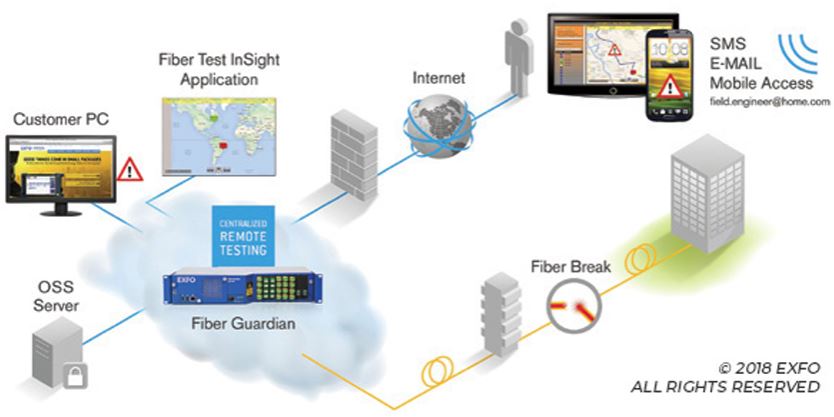
Shelf-mounted OTDRs are already a staple in central offices, but they typically don’t offer visibility to the outside plant (OSP) staff that enable them to resolve events as quickly as they would like. Information derived from these systems is often incomplete, and they require excellent records to understand exactly where a break might occur based on the OTDR trace. Fiber versus cabled length, slack loops, and risers are just a few reasons why OTDR traces might not pinpoint the exact geographical location of the event.
There is a Remote Fiber Test System (RFTS) today that supports integration with multiple GIS and reporting software that is 100% web-based. Alerts can be generated by the system to immediately notify the appropriate parties that there is an issue. These notifications may be transmitted via text message (SMS), email, or SNMP notifications. Furthermore, if the RFTS system is integrated into a GIS or if it uses its own mapping tool, the GIS tool can give and display accurate geographical locations based on GIS documentation. The software logging the events can prioritize by severity (i.e. macrobends versus a break) allowing technicians and their managers greater efficiency in repairing the network.
These systems can run as standalone units or combined to monitor multiple fiber routes to get a complete view of the network operations. The ability to build-as-you-grow allows for flexibility in capital expenditures with options to layer advanced software suites with in-depth analytics to better suit a wide range of budgets and reporting requirements.
The predictions for connected devices in the IoT realm range from extraordinary to unbelievable. If the invention of the smartphone was any indication, who would have predicted the number of applications that would develop for any conceivable purpose? With these three connected technologies, you could gain invaluable insight into the network for security, damage prevention, and efficiency. Network operators are already in the driver’s seat for the Internet of Things… the time has come to take advantage of it.
This article was kindly contributed by Matt Brice, Product Sales Manager, Comstar Supply. We’ve brought together the distribution and manufacturing communities to publish
“The Contractor Chronicles”, a new publication focused on network contractors and operators. The inaugural issue includes the five things you need to know before installing cable or learn from some of our leading partners on service delivery, the FTTH ecosystem, fusion splicing, and power meters.


 Besides enhancing your viewing experience, higher resolution 4K Ultra HD TVs also allow you to sit closer to a screen and/or view a larger screen without seeing pixilation of scenes. That’s why it’s possible for manufacturers to make larger TVs with screen sizes of 80 inches and above while still providing excellent picture quality. By enabling superior picture quality on large screens and enhanced picture quality even up close, 4K Ultra HD technology gives you more freedom in your home to sit wherever you like and watch on a larger screen without compromising clarity. All in all, the enhanced resolution in 4K Ultra HD products helps deliver a more detailed, immersive, and realistic entertainment experience.


 DVI (Digital Visual Interface) offers a high-bandwidth, digital-to-digital video connection that bypasses the digital-to-analog and analog-to-digital conversions necessary between components with only component video connections. Eliminating the undesirable artifacts of such conversions results in a more faithful reproduction of the original signal. DVI connections may optionally incorporate the High Definition Content Protection (HDCP) protocol, enabling them to pass copy-protected digital broadcast content (if this capability is present, it’s usually indicated by the designations “DVI-HDCP” or “DVI with HDCP”)
 Though inferior to the digital connections listed above, component video is superior to both S-video and composite video because it provides improved color purity, superior color detail, and a reduction in color noise and NTSC artifacts. The 3-plug video output of a DVD player sends/receives the luminance (Y) and 2 color signals, each on a separate colored RCA cable.
 An S-video connection is much better than a composite video connection, but it is not as good as component video. This higher quality video input/output segregates chrominance (color) and luminance (light) signals for excellent reproduction from high-quality video sources such as S-VHS, Hi8 and DVD players.
 Making a digital connection (optical or coaxial) between your receiver and DVD player or CD player is a great option. A digital stream sends unprocessed sound information to your receiver (which, as a general rule, has a better digital-to-analog signal processor than a DVD or CD player) to be decoded and amplified. (In the case of SACD or DVD-Audio players, a 5.1-channel analog connection is necessary.) An optical digital connection sends signals in the form of light, as opposed to electrically. Optical cables have the advantage of being immune to EM and RF interference.
 Coaxial A/V cable (also know as RF cable) connects your cable box or digital satellite box to your TV. It can also be used to connect a VCR to your TV (but composite or better A/V cables are preferable). If your TV only has coaxial RF inputs, you can use a video switcher and RF modulator to hook up advanced sources like DVD players or home gaming systems (but picture and sound quality is not nearly as good as with composite, S-video or component video connections).
 IEEE1394 (or FireWire or i.LINK) is a flexible digital connection that can pass HDTV signals using MPEG2 video to devices such as high-definition D-VHS recorders. It also supports daisy-chaining.
 Multicom’s New Fiber Optic and Network Products are Leading the Way
 What is the Purpose of a Cable Jacket?


 Older devices use analog signals, while newer ones use digital signals, and they each have different types of connectors to get everything to work together. In a home theater, analog signals usually use one of two different connector types: composite or component. Composite RCA cables feature one yellow connector for video, and red and white connectors for audio. Component cables use red and white audio connectors, but they divide the video into three components: one for luma (brightness) and two for color information. This is known as YPbPr component video.


 2. Test Station
 4. Ground
 1. Fiber OD
 4. Locations of 90s + Loops
 With the introduction of the 90S+, Fujikura has also introduced the new Active Fusion Control (AFC) technology to further improve the dependability and consistent performance of core alignment fusion splicers. With each generation of fusion splicer development, Fujikura has continued to innovate and improve the state of the art in fusion splicing, and AFC in the 90S+ is the latest example.


 delivering 15 watts of power. This would accommodate a typical WiFi access point.
 Remote Fiber Test Systems