Multicom’s Certified Fiber to the Home Professional (CFHP) as well as System Engineers often do trainings – both in-house or at your premises
Everything You Need to Know – Resource Guides from Data, Video and Fiber Optics, to our exclusive and odd-ball Did You Knows
Welcome to The SCOOP, an exclusive in-house publication solely focused on bringing the electric cooperative, broadband, and manufacturing communities together with relevant information about products and issues impacting the market.

Included in this issue:
Included in this issue:
Included in this issue:
Read Our Most Recent Articles:
Quick Fact: Fiber Optic technology is one of the “greenest” out there. It takes a lot more energy to send a sustained electric signal than it does a single flash of light. In this day and age where consumption has to be kept to a minimum, lower energy output and consumption means a smaller carbon footprint on the environment.
Quick Fact: Because fiber optic cable transmits light, not electricity, they don’t degrade over time like wire cables. They’re not affected by water, wind, ice, or extreme heat! Though they’re not immune to damage, they can take a lot more abuse than wire cables. In the long run, this means less cost for both you and the consumer.
Optical fiber uses light instead of electricity to carry a data signal. This is unique because fiber can carry high bandwidth signals over long distances without degradation. Copper can also carry high bandwidth, but only for a few hundred yards – after which the signal begins to degrade and bandwidth narrows. Optical fiber has been used in communication networks for more than 30 years, mostly to carry data traffic from city to city or country to country. With its advantages over copper, fiber optic networks have revolutionized long-distance phone calls, cable TV and the Internet.
However, to many people, even veterans of the industry, there are many industry terms that are still mysterious or unclear. Don’t worry, at Multicom we believe in keeping it simple. Let’s try to make sense of it from the beginning:
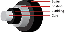 Optical Fiber: Thin strands of highly transparent glass or sometimes plastic that guide light.
Core: The center of the fiber where the light is transmitted.
Cladding: The outside optical layer of the fiber that traps the light in the core and guides it along – even through curves. This layer is never stripped off the fiber.
Buffer Coating or Primary Coating: A hard plastic or acrylic coating on the outside of the fiber that protects the glass from moisture or physical damage.
Mode: A single electromagnetic field pattern (like a ray of light) that travels in fiber.
Multi-mode Fiber
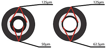
Multi-mode Fiber: Has a bigger core (almost always 62.5 microns – a micron is one one-millionth of a meter – but sometimes 50 microns) and is used with LED sources at wavelengths of 850 and 1300 nm for short distance, lower speed networks like LANs (Local Area Networks).
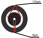
Singlemode Fiber
Singlemode Fiber: Has a much smaller core, only about 9 microns, and is used for telephony and CATV (Cable TV) with laser sources at 1300 and 1550 nm. It can go very long distances at very high speeds but with higher cost.
Fiber termination is an important part of fiber optic cabling. Having an idea of these terms in termination will help:

Multi-mode has orange cable, Singlemode has yellow cable
Connector: A non-permanent device for connecting two fibers or fibers to equipment where they are expected to be disconnected occasionally for testing or rerouting. It also provides protection to both fibers.
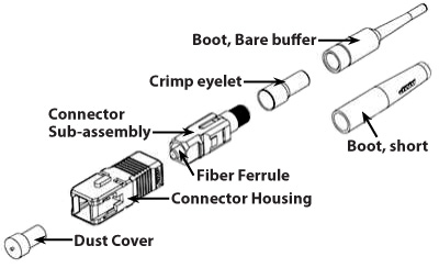
Components of an SC Connector
Ferrule: A tube that holds a fiber for alignment, usually part of a connector.
Splice: A permanent joint between two fibers.
Mechanical Splice: A splice where the fibers are aligned and joined by a mechanical splice device.
Fusion Splice: A splice created by welding or fusing two fibers together.
Cable Management: Terminations and Splices require some hardware for protection and management: patch panels, splice closures, ODF (optical distribution frame), FTB (fiber termination box) etc.
Some of these terms you may be familiar with by knowing coiax cabling, but they vary in reference to fiber optics, so let’s review:

Save time and money. Multicom has Certified Fiber to the Home Professionals (CFHP) on staff who can take all of this into account and design the system that’s right for you.
Attenuation: The reduction in optical power as it passes along a fiber, usually expressed in decibels (dB).
Bandwidth: The range of signal frequencies or bit rate within which a fiber optic component, link or network will operate.
Decibels (dB): A unit of measurement of optical power, which indicates relative power. A -10 dB means a reduction in power by 10 times, -20 dB means another 10 times or 10 times overall, -30 means another 10 times or 1000 times overall and so on.
Micron (um): A unit of measure used to measure wavelength of light.
Nanometer (nm): A unit of measure used to measure the wavelength of light (meaning one one-billionth of a meter).
Optical Loss: The amount of optical power lost as light is transmitted through fiber, splices, couplers, etc, expressed in dB.
Optical Power: is measured in “dBm”, or decibels referenced to one milliwatt of power. while loss is a relative reading, optical power is an absolute measurement, referenced to standards. You measure absolute power to test transmitters or receivers and relative power to test loss.
Absorption: Absorption occurs in several specific wavelengths called water bands due to the absorption by minute amounts of water vapor in the glass.
Scattering: The change of direction of light after striking small particles that causes loss in optical fibers and is used to make measurements by an OTDR
Wavelength: A term for the color of light, usually expressed in nanometers (nm) or microns (m). Fiber is mostly used in the infrared region where the light is invisible to the human eye.
At Multicom, we strive to not only provide you with the products needed for the end to end integration of a fiber optic and CATV distribution systems; but most importantly, we stress ‘personal service’. When you call us a real person answers the phone! You will be then be transferred to a qualified sales or technical engineer with the experience and expertise to provide the products and service you need, or answer your questions. We value the relationships we have built over the 33 years we have been an industry leader.

Purpose Drives Technology Forward
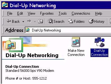 If you are old enough, there is no way you will ever forget unplugging the cord of your phone and into the back of a dial-up modem. The bing bing bzzzz of the modem as it ‘shook hands’ with the carrier, and the anticipation of hopefully, because it was always tenuous, being connected to the World Wide Web – the Internet. It took immense patience (the maximum transfer speed at that time was 56 Kbps, if you were lucky), but eventually, a screen on your computer would magically appear. From there you could actually surf the web for anything of interest. It seemed like if you had the time and patience, the world was literally at your fingertips. It was exhilarating and fun, but slow and tedious, and often ended in frustration.
Fast-forward to today. It’s nearly impossible to conceptualize the evolution of that primitive dial-up modem to the incredibly advanced technology that we depend on for so many of the essential components of our lives that we now take for granted. All technology is born out of purpose, and there is no better example of this than the Internet – human interconnectivity, the various ways that we all communicate with each other and seek to advance our knowledge. Believe it or not, all of this has led us to one primary technology: The incredible advantages of fiber optics and networking, and how like all technologies, it is evolving for our benefit. And there is no end in sight for the power of light traveling through glass cable.
No Power Required: The Evolution of the Passive Optical Network (PON) Continues to Adapt
As fiber optics evolved, so did the backbone of the fiber optic network. After all, there has to be a way for everyone to interconnect in a way that takes advantage of all of the benefits of fiber optics. It gets a bit complicated but PON technology originated in the 1990s and has continued to develop through multiple iterations with differing wavelengths, speeds, and components emerging as the technology has evolved and improved.
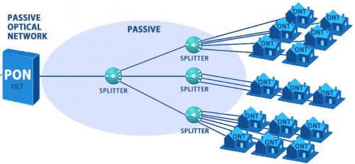
Between the OLT and ONT: No power is required
The common denominator of all fiber optic PONs remains the unpowered or passive state of the fiber and its splitting or combining components. There are no active components such as optical amplifiers, which would require power present in the network. This is the key to the unlimited broadband potential of a Passive Optical Network. A PON uses unpowered fiber optic splitters to enable a single optical fiber to serve multiple end-points such as customers instead of providing individual fibers between the central office (hub) and the customer.
According to different terminations of PON, the optical network can go as far as fiber-to-the-curb (FTTC) which gets it close, fiber-to-the-building (FTTB) which gets it closer, and fiber-to-the-home (FTTH) which brings it all the way to or into the home or office of the end user. In this case, you can have fiber from end to end, maximizing the potential of fiber optics.

As mentioned, PON technology is ever-evolving, and to get to where we are now, we have gone through various types of PON topologies, briefly:

Basic PON architecture: OLT <–> Splitter <–> ONT
It doesn’t stop there. At this point, we have only scratched the surface of PON technology because it has evolved beyond mere GPON. Now there is:
Maybe this will make things clearer:
| Specification | GPON | XGPON | XGSPON |
| Max Speed Downstream | 2.488 Gbps | 9.953 Gbps | 9.953 Gbps |
| Max Speed Upstream | 1.244 Gbps | 2.488 Gbps | 9.953 Gbps |
| Max Distance | 37 miles (60 km) | 62 miles (100 km) | 62 miles (100 km) |
| Max Split Ratio | 1:128 | 1:256 | 1:256 |
As PON evolves, new and more advanced equipment is used on both ends of the fiber optic networks. On the transmit side there is the OLT, or Optical Line Terminal, and on the received/retransmit side (or customer/end-user), there is an ONT, or Optical Network Terminal (or ONU, Optical Network Unit). The ONT is the modern version of that old dial-up modem, acting as the device that receives downstream data and retransmits data upstream to and from the user. Multicom stocks XGSPON OLTs and ONTs that can be integrated into today’s most sophisticated optical networks.
What is on the Horizon?
Even more capacity and higher speeds, of course. Looking beyond XGSPON there is NGPON2 which utilizes Wavelength Division Multiplexing (WDM) with multiple 10 Gbps wavelengths, both up and downstream, to deliver a symmetrical 40 Gbps service. NGPON2 uses different wavelengths of GPON and XGSPON to allow for service to co-existence on the same PON.
As PON technology continues to evolve and improve, the strategic and economic advantages of PON deployment will become more compelling. As speed demands continue to increase year over year, the evolution of the PON will continue to adapt. XGPON, XGSPON, and NGPON2 will provide an upgrade path to the future of PON technology that is currently beyond our capabilities – but not beyond the capabilities of fiber optic cable, which gave birth to the term ‘future-proof’. This natural evolution will help to continue the expansion of Passive Optical Networks into the smart cities, universities, hospitals, and corporations that make up the connected world of today and tomorrow.
How Does PON Get from Point A to Point B, and Back?
We have covered a lot about fiber optic networks and how they have evolved in a way that increases capacity and speed. But in this article, we have only touched on the equipment involved. To learn more about PON products and how they interact, please see:
For the first 25 years of the industry’s existence, broadcast retransmission (especially distant stations), was about the only thing they had to sell. Many systems originated local programming and carried public, educational and government access programming, but these services didn’t sell many subscriptions.
The term CATV originally stood for Community Antenna TV. Somewhere around the mid-70s, when CATV companies began carrying satellite-delivered non-broadcast programming, the term CATV morphed into Cable TV.
PVC – Polyvinyl Chloride – is a soft jacket used indoors and outdoors. IMSA 19-1 has a PVC jacket.
PE – Polyethylene – is a more rigid jacket and is primarily used outdoors. IMSA 20-1 has a PE jacket.
Both can be used for aerial and duct applications. Because it is softer and more pliable, PVC has a smaller bend radius than PE.
The only difference between IMSA 19-1 and IMSA 20-1 is the type of jacket.
IMSA 19-1 is constructed with a Polyvinyl Chloride (PVC) jacket, and IMSA 20-1 has a Polyethylene (PE) jacket.

Broadband has become an essential utility for people around the world. It powers the digital economy; it makes applications such as remote learning and telemedicine possible; and it sets the stage for a future where virtual reality, augmented reality, and the metaverse are commonplace. Unfortunately, true broadband is still out of reach for many.
According to the U.S. Department of Commerce and the NTIA, 22.5% of U.S. households are estimated to not have access or the ability to purchase broadband internet. Furthermore, 17.3% of rural households and 1.2% of urban households lack fixed terrestrial access to speeds greater than 25 megabits per second (Mbps) for download and 3 Mbps for upload, which is considered to be unserved according to the FCC’s Broadband Deployment Report.
In support of closing this digital divide, governments and municipalities have introduced initiatives that provide billions in funding to build out broadband networks and bring high-quality connectivity to all, especially low-income neighborhoods and rural communities. In the U.S., these programs include:
• The Rural Digital Opportunity Fund (RDOF)
• The Consolidated Appropriations Act, 2021 (CAA)
• The Coronavirus Aid, Relief, and Economic Security Act (CARES)
• The Infrastructure Investment and Jobs Act (IIJA)
• The American Rescue Plan Act of 2021 (ARPA)
Even with money flowing into the broadband buildout, there are still plenty of challenges to overcome and issues to consider. In this article, we’ll discuss some key considerations that may help with your network planning.
Understanding density’s impact on fiber installation costs
Population density, i.e. homes per square mile, typically comes to mind as a key metric in calculating the return on investment potential for fiber broadband buildouts. But for service providers targeting rural markets, homes per linear mile is a much more useful measurement. That’s because rural broadband networks typically follow the long roads between homes, and the lengths of those spans are key drivers of both material and labor costs. Densities below eight homes per linear mile require special consideration since they create the greatest delta between infrastructure costs and revenue opportunities.
Choosing the right broadband technology
Delivering broadband to everyone, everywhere requires service providers to evaluate a mix of technologies leading with fiber to the home (FTTH) due to its future-proof capabilities. Service providers are also evaluating fixed wireless access (FWA) and, in some cases, low earth orbit (LEO) satellite technologies, which can be deployed relatively quickly but can be limited in their ability to meet long-term capacity needs. The right choice for a given geography or application will come down to the important dynamics of bandwidth, economics, and homes per linear mile. While it may not be perfect for every geography or application, expect FTTH to play a key role in most broadband buildouts due to its capacity, scalability and expected lifespan.
Considering PON’s distance thresholds
Passive optical network (PON) technology, the leading choice for FTTH deployments, has a distance threshold between the optical line terminal (OLT) and the last optical network unit (ONU). Therefore, it may not seem practical for rural locations with significant distances between central office facilities and subscriber homes. But new remote OLT solutions can extend PON’s launch point deeper into the network and allow even the most remote subscribers to take advantage of high-quality broadband. This makes FTTH an option in locations where it was once impractical.
Navigating a constrained labor market
The pool of skilled labor for network, cable and field technicians is already stretched thin in the telecommunications services market. As broadband for everyone marches on and service providers build out new network facilities and connect new subscribers, the labor shortage is expected to grow. While training will help fill in the labor and skills gap, now is the time to consider technologies that simplify fiber installation, hardware provisioning, troubleshooting and repair to maximize the skilled labor resources we have in the broadband industry.
Easing operational expenses
Even though FTTH technology is easier to maintain compared to other alternatives, the management and maintenance of fiber networks can create significant work—and significant costs. That’s why it’s important to consider the expenses of provisioning services, upgrading networks, finding issues, and fixing problems. In rural markets, where technicians often need to travel long distances to upgrade, maintain, troubleshoot, and repair the network, small savings can add up fast.
 Deploying fiber faster
Broadband for everyone may not happen overnight, but it will likely happen fast thanks to the perfect storm of exploding bandwidth demand and significant new funding. For service providers, seizing this opportunity begins by getting educated on the process of securing grant funding right away—and extends all the way to getting new fiber networks and segments built out as quickly as possible. By moving fast, service providers can connect subscribers to their networks in the near term, while helping to stave off competition and expediting their returns on fiber investments.
Broadband for everyone starts now
While broadband for everyone is an ambitious goal, it is achievable. One of the first steps of the journey is for service providers to recognize the challenges, opportunities, and economic realities of network deployment in underserved markets. The CommScope team is committed to examining these issues in detail as our broadband for everyone campaign continues.
This article has been kindly contributed by Craig Culwell, Commscope

Starting a broadband business from scratch can be a daunting task, but with the right approach and guidance, it is possible to build a successful enterprise to serve your community and stakeholders. The broadband industry has seen steady growth in recent years, and as demand for faster internet speeds and greater connectivity continues to rise, the market presents an exciting opportunity for communities and infrastructure investors.
As today’s utilities face rising costs, grid resiliency challenges, unpredictable extreme weather conditions and potential cyberattacks, many electric cooperatives are interested in the opportunity to transform their business by building a new broadband network. Beyond being a smart investment that enables a more resilient electric grid, fiber infrastructure allows rural cooperatives to better serve their communities by offering affordable, high-speed internet services to bridge the broadband gap.
To build a broadband business from day one, there are several important considerations to keep in mind. These include securing funding, establishing sound business management and governance practices, implementing effective network operations strategies, and focusing on continued improvement.
Lay the Groundwork
One of the first steps in building a broadband business is to secure funding. Federal and state governments have tried to make significant investments in expanding broadband access in rural areas and other underserved communities, and communities and other organizations can take advantage of these opportunities to secure funding for their projects.
There are several grant programs for broadband, including the Infrastructure Investment and Jobs Act (IIJA), Broadband Equity, Access and Deployment (BEAD) fund, USDA’s ReConnect Program, and the American Rescue Plan Act (ARPA). These grant programs provide funding for infrastructure development, network expansion and other initiatives that support broadband deployment. These funding sources do come with quite a bit of competition, paperwork and requirements to be met, however, so this might require the help of an expert to ensure a strong and complete application.
When applying for grant funding, it is essential to have a clear and compelling business plan that outlines the scope of the project, the target market and expected outcomes such as greater access and affordability. Successful grant applications also demonstrate a strong commitment to sustainability and long-term viability, which is critical for securing ongoing funding and support.
 Likewise, private capital is a growing part of the broadband story as well, and many investors are looking to find ways to be a part of solving the digital divide while gaining a stable and long-term investment.
Managing expectations also will be important as the planning process moves forward. Implementing a new business model may require more leadership oversight to align to internal targets, such as reaching a break-even point quickly. Furthermore, regulatory agencies have expectations about reporting deadlines, and community stakeholders will anticipate regular updates as they become invested in the project.
A good example of how to manage expectations is the case of a municipal broadband utility in Fairlawn, Ohio, that continually informs stakeholders about future expansion plans and funding needs. This constant communication effectively provides transparency for the community as well as marketing the utility’s broadband service to potential customers.
Balance Business Priorities
To build a successful broadband business, it’s important to establish sound business management and governance practices from the outset. This includes developing a clear organizational structure, creating effective policies and procedures, and implementing strong financial management practices.
It’s essential to have a strong leadership team in place, with individuals who have the experience and expertise needed to guide the company through the challenges and opportunities of the broadband industry. This team should include professionals with a deep understanding of the technology, regulatory environment and market dynamics of the broadband industry.
To deliver reliable, high-quality broadband service, effective network operations strategies are critical. This includes investing in state-of-the-art equipment, software and infrastructure, as well as developing strong relationships with vendors, suppliers and other key stakeholders.
Additionally, it’s also vital to have a robust network operations center (NOC) in place, staffed by trained professionals who can monitor network performance, troubleshoot issues and ensure that service levels meet or exceed customer expectations. There are many ways to achieve these end goals. For some cooperatives, the best answer may be to seek help from vendors with established expertise, NOC availability, and access to equipment and materials to keep the project on track.
In many cases, operating a broadband network may not be within the scope of responsibilities for existing personnel. When hiring staff, it’s essential to consider how their training will be handled, and if they will work on all aspects of the business or just focus on a single area. By cross-training employees, a cooperative can reduce operating costs, optimize productivity and build skill redundancies.
On the other hand, when the expertise isn’t available in-house, it often may be difficult to find the right personnel even throughout the region. In these instances, or if a cooperative chooses to simply focus on their core business, broadband challenges may be best solved by augmenting resources with the help of an expert network systems integrator, like Fujitsu, bringing years of networking experience and dedicated resources to the task at hand.
Regardless of whether management is outsourced or handled in-house, how can the cooperative balance the business needs and objectives between being a broadband service provider and providing electric service?
Organizational planning is key to clarify how much time is being spent on what, who will handle different functions, and ensure reliability on both sides, in order to make sure customers are not negatively impacted by a sudden event.
Don’t overlook the possibility that an actual separation between the two businesses may be necessary to meet expectations of staff and stakeholders. In fact, when Craig-Botetourt Rural Electric Cooperative (CBEC) in southwestern Virginia decided to offer broadband services, the State Corporation Commission of Virginia required the cooperative to establish a subsidiary to handle administration of their high-speed broadband business. In addition to enabling the management team and board of directors to abide by regulatory requirements, this separation also helped to provide greater clarity on what resources were allocated to each function.
Build for Tomorrow
 Finally, to build a successful broadband business, it is important to focus on continuous improvement. This includes investing in your network to stay on the cutting edge of technology, seeking out new opportunities for growth and expansion, and continually refining business processes and practices to optimize performance.
Even after the milestone of turning up broadband service has been achieved, it’s vital to keep planning for the future. What is the best way to expand and improve service, and how can operations be simplified? The best practice is to implement a formal process of continuous improvement, which might include staff training, regular input from stakeholders, a review of lessons learned, or talking to industry consultants and vendors for new ideas.
Looking forward to the future, be sure to keep new customers’ needs in mind to align current service offerings and future network upgrades. For example, smart agriculture applications are quickly being developed, which might involve different technologies versus a typical fiber-to-the-home (FTTH) broadband network. Other potential use cases to consider include communications for maintenance drones and the needs of local government agencies, schools or libraries.
Plan to Succeed
One way to achieve these objectives and build a successful broadband business from day one is to work with a turnkey partner. A turnkey partner can provide expertise in securing federal grant funding, establishing sound business management and governance practices, implementing effective network operations strategies, and focusing on continued improvement.
Working with the right partner can also help cooperatives navigate the complex regulatory environment of the broadband industry, stay on top of emerging trends and technologies, and identify new opportunities for growth and expansion.
Building a successful broadband business from day one requires careful planning, sound business management and governance practices, effective network operations strategies and a commitment to continuous improvement. Working with a turnkey partner can help communities and investors achieve these objectives and build a thriving enterprise in the dynamic and exciting broadband industry.
With a strategic investment in fiber broadband, electric cooperatives can do more than just survive — they can grow and flourish for the future. More importantly, the communities they serve also will thrive, thanks to the benefits that broadband access delivers: quality of life, enhanced business prospects, modernized services and long-term growth. While the path to broadband may seem a bit rocky at first, starting strong on solid footing with the right partner by your side means you can be confident of success for the long haul.
This article was kindly contributed by: Anthony Bednarczyk, Broadband Practice Leader, Fujitsu

Wide area networks have always been critical to energy companies. But the solutions applied today might not be sufficient for the demands of the future as legacy technologies become obsolete and new protocols must be supported. The digital transformation is also impacting networking technologies and forcing a convergence to IP and Ethernet. What’s more, with distributed energy production, there is a need to push advanced control technologies from core to edge. This extends the coverage of the wide area network but also requires precise synchronization to be delivered to remote sites in the power grid. The migration of the wide area network is a highly complex task, which becomes even more complex with the changing threat landscape and the increasing number of sophisticated attacks.
This article highlights proven methods for converging legacy communication networks and making them future-proof and secure. It explains the relevance of resilient, accurate timing and shares best practices for robust synchronization networks. It also highlights some solutions from ADVA that can help you make the transition.
Towards a future-proof WAN architecture
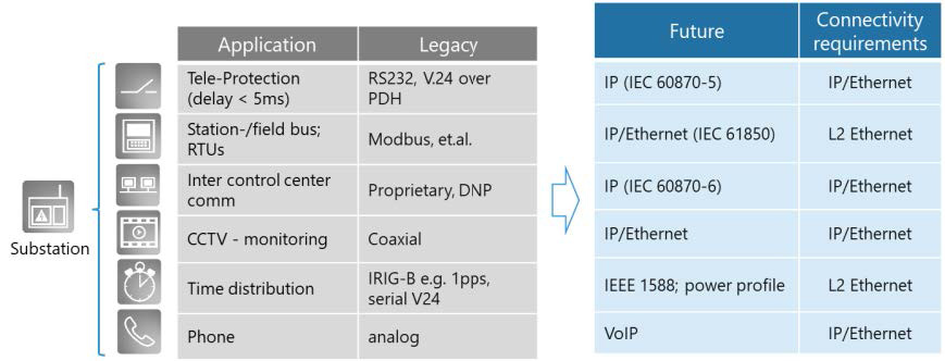
Figure 1: Digital transformation of power grids
Historically, energy companies have installed a variety of application-specific solutions. Supervisory control and data acquisition (SCADA) systems, industrial control systems (ICS), solutions for tele-protection, and intra-office systems use specific communication protocols. Proprietary protocols and purpose-built hardware have successfully worked in the past, but this approach will not meet future needs. Figure 1 outlines the technology convergence as it happens in power grids today.
While SDH/PDH technology is still used in the power utility WAN, many operators have complemented, or substituted, those legacy networks with IP and MPLS technology. In many cases, MPLS-TP is being applied as this specific flavor of MPLS uses centralized provisioning of label-switched paths, and is operationally aligned with SDH/PDH networks, simplifying its introduction and adoption.
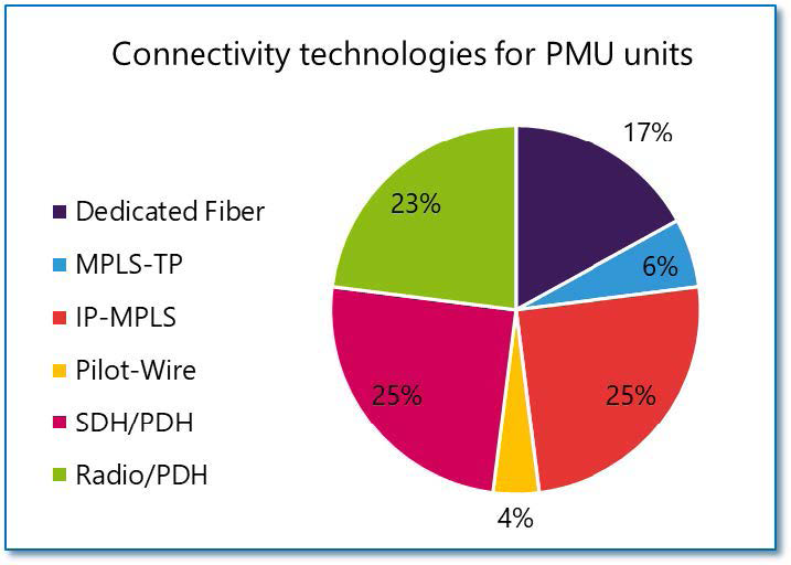
Figure 2: Connectivity technologies for phasor measurement units (PMU)
The International Council on Large Electric Systems (CIGRE) Study Committee D2, December 2021 recently performed a survey on the current state of telecommunications in power utilities. The results shown in Figure 2 give a good insight into the state of migration from TDM to packet:
While roughly a third of this traffic is transported over MPLS, there is still a large proportion using legacy technologies.
Technology migration happens gradually. A connectivity network will need to transport legacy TDM but also MPLS traffic. MPLS-TP may be used for a tactical smooth transition from TDM to packet network technologies. However, as it isn’t widely supported by suppliers and it is getting competition from segment routing, this technology is unlikely to continue. Segment routing combines the best of IP and MPLS while including TP management practices.
Vertically integrated solutions are difficult to migrate and align with changing requirements such as MPLS technology evolution. In consequence, we should architect networks in a disaggregated and open way with the possibility to select best-in-class technology for MPLS and DWDM transport. As shown in Figure 3, open optical transport technology can easily be combined with hybrid TDM/packet technologies such as those from our partner OTN Systems or a pureplay ADVA FSP 150-XG400 packet solution.
Secure transport in the WAN is essential for protecting critical infrastructure from cyberattacks.
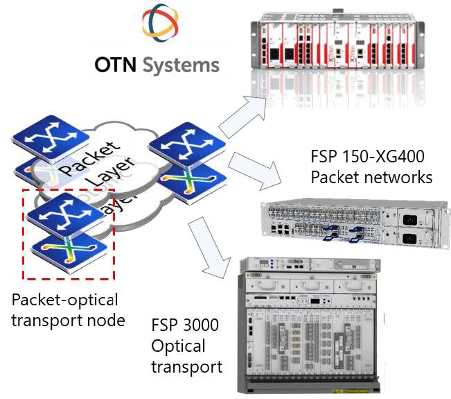
Figure 3: Disaggregated design of the WAN
In many countries, regulatory obligations require the encryption of mission-critical communication to assure business continuity. The packet network and optical network devices should be able to encrypt network traffic at line rate. Our FSP 3000 open optical transport platform supports line-rate encryption of wavelengths while MACsec+ provides end-to-end encryption at the FSP 150 packet layer.
Failures of network components or fiber breaks cannot be avoided, but the impact can be minimized with resilient and well-monitored networks. Protection mechanisms such as optical path protection, Ethernet ring protection, or redundant MPLS paths can instantly repair network failures in an automated way. However, it is still necessary to identify the failed component and initiate immediate repair. This is done through sophisticated OAM capabilities at the optical, Ethernet, and IP/MPLS layer.
A failure in the passive fiber network can be detected and localized within milliseconds with the help of OTDR-based fiber monitoring solutions. What’s more, with the help of fiber sensors for security and environment applications, any threat to the physical infrastructure can be instantly detected.
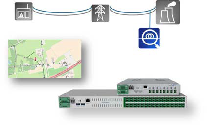
Figure 4: Fiber monitoring for immediate failure detection and localization
Protecting sub-stations from cyber threats
With the emergence of distributed power generation, automated control is moving from primary to secondary substations and towards decentralized solar power plants and wind farms. Distributed power generation creates a need for visibility and control of a high number of remote energy production sites.
As operational technology (OT) is moving to the edge of the power grid, standardized and innovative solutions will be applied, converging the previously applied operational protocols on a common IP and Ethernet transport layer.
The digital transformation at the substation will not happen with a forklift upgrade but in a seamless migration, leveraging proven technologies and migrating towards a converged IEC 61850 automated substation architecture. During this transition period, a diverse set of technologies will need to be supported at substations. Established asynchronous and synchronous interfaces such as RS232 or STM1 or application-specific interfaces such as C37.94 for teleprotection will be applied while TDM network interfaces migrate to Ethernet over DWDM.
Most legacy technologies have not been designed with security in mind. In some cases, operating systems are now reaching end-of-life and are suffering from a lack of security patches. This results in the need for a security architecture at a substation that prevents vulnerable components and sub-systems from any access.
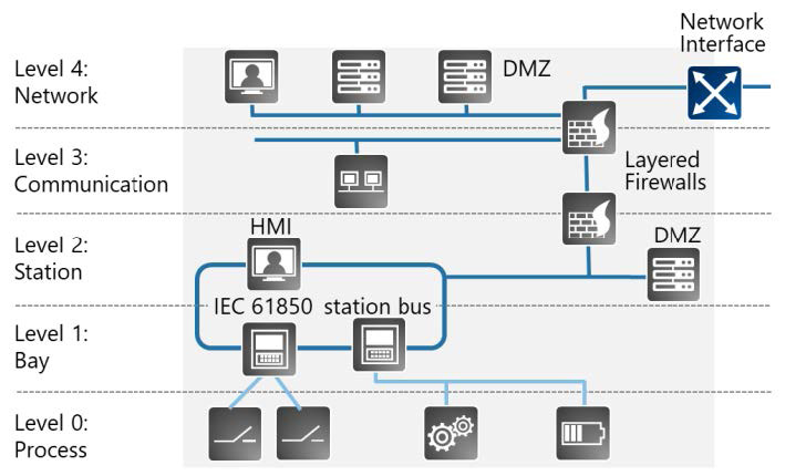
Figure 5: IEC 62443 cybersecurity architecture for industrial control systems
With IEC 62443 a comprehensive framework is available, guiding the implementation of cybersecurity in industrial control systems (ICS). Based on a risk assessment, it specifies a zoned architecture to protect the most critical assets with multiple layers of defense.
National regulators are also requesting critical infrastructure to implement controls for assuring business continuity. This makes general security controls such as encryption of the connectivity network, firewalls, and intrusion detection systems a requirement.
In Germany, for instance, the Information Security Act 2.0 creates a need to identify and report attacks to critical infrastructure. This isn’t an easy task, as present substation applications do not provide an easy way to do this.
ADVA is responding to this need with a software-centric security solution, optionally supported by a secure and environmentally hardened edge compute node. Monitoring of ICS/ SCADA traffic can be done most efficiently by software probes. Several suppliers provide the appropriate software applications, but they do need to run in a protected, security-hardened environment.
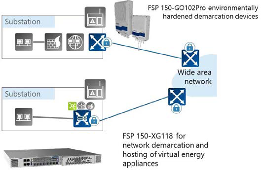
Figure 6: Securely connecting substations with the wide area network
Ensemble Connector is a hosting platform and network operating system with comprehensive protective controls. It can be installed on an FSP 150-XG118 (CSH), which is an edge compute node featuring advanced encryption for securely connecting a substation to other sites of the power grid. Ensemble Connector can also be installed on x86 based COTS servers; for utility use cases the servers will need the appropriate security features.
ADVA is working with leading suppliers of software for monitoring substation traffic such as Nozomi or Palo Alto to identify any malicious activities targeting both the IT and OT network.
Making synchronization networks robust and secure
Synchronization and timing have been a requirement for the PDH/SDH communication network in the past. Many protocols applied at substations such as DNP or GOOSE require timing, but only with moderate millisecond accuracy. With the IEC 61850 substation automation standard and technologies for precise localization of network faults, sub-microsecond timing will need to be assured. While frequency synchronization is delivered from the connectivity network by means of SyncE, time of day (ToD) information is frequently provided by Global Navigation Satellite Systems (GNSS), such as GPS, located at each and every site.
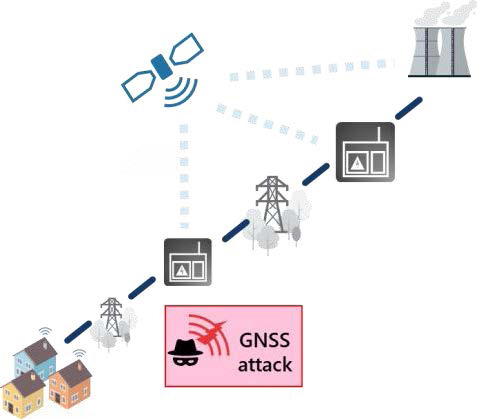
Figure 7: GNSS attacks threaten business continuity
In consequence, many power utilities apply a high number of GNSS receivers at their substations for access to the precise time. There are growing concerns about disturbances caused by jamming and spoofing attacks, solar events, weather patterns, etc. The operational complexity of thousands of GNSS receivers also adds considerable cost. What’s more, these receivers are often not integrated into central management systems. Consequently, problems, failures, and attacks against timing networks at substations might pass unnoticed until major failures in the power grid occur.
There is an urgent need for a highly resilient and accurate synchronization architecture in power utilities. Delivering accurate synchronization with the packet network is a sensible approach to initially backup GNSS-delivered timing and eventually become the main timing source. This requires timing-aware switches and routers supporting SyncE and PTP in combination with highly stable core grandmasters backed up with ultra-stable cesium atomic clocks to meet even the most stringent enhanced primary reference time clock (ePRTC) specifications.
As mentioned before, multiple protocols need to be supported at substations. This is also true for the synchronization network, which needs to support legacy interfaces such as IRIG-B at substations or NTP.
ADVA’s Oscilloquartz division provides the most comprehensive assured positioning, navigation, and timing (aPNT+™) technology for resilient power grid timing. With multi-technology substation grandmasters, modular and redundant core grandmasters in combination with proven, ultrastable cesium clocks, this comprehensive solution portfolio can be adapted to any power grid timing need. What’s more, the unique AI-empowered Ensemble Sync Director management solution assures accuracy of timing at any site, even analyzing data from any third-party GNSS receiver.
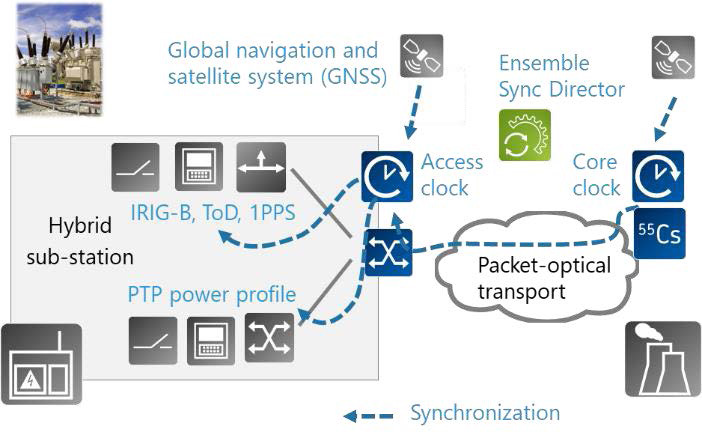
Figure 8: Providing accurate and resilient substation timing
Technology experts are joining forces
Communication networks for power utilities are covering applications in very different competence domains. There are IT applications that need standard IP connectivity over fixed and wireless networks but also utility OT applications such as SCADA and tele-protections with domain-specific protocols and interfaces. Suppliers with OT experience and products will work with suppliers addressing the IT and service provider market in order to combine their solutions and meet both current and future communication requirements.
This is why OTN and ADVA have joined forces to pre-integrate and test a network solution for power utilities. Both companies have a leading portfolio in their home markets, and their combined solution perfectly meets the most demanding communication requirements of critical infrastructures.
OTN Systems provides a market-leading network solution for specific industrial segments, including public networks, light rail, oil and gas, power utilities, and mining. With its new product line, XTran, the company is well-positioned to offer market-leading solutions to those enterprises.
What’s more, ADVA is joining forces with independent software vendors providing software applications at the substation to monitor and protect the IT and OT network.
Jointly with our partners, ADVA offers a comprehensive, secure, and resilient wide area network for power utilities, featuring accurate and robust synchronization and supported by a powerful end-to-end management system.
The ADVA solution for wide-area networks
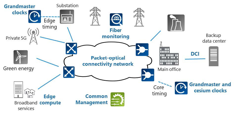
Figure 9: ADVA solution overview for power grids
ADVA’s carrier-grade network products are a perfect solution for communication networks with power utilities, combining operational simplicity with high availability and resilient designs. In addition, ADVA offers infrastructure assurance solutions for passive, in-service monitoring of fiber and sites. Oscilloquartz, a fully-owned ADVA company, is a market-leading supplier of synchronization solutions. Its portfolio was recently extended with PTP power profile, NTP server, and IRIG-B interfaces for the seamless migration of legacy synchronization solutions toward highly accurate PTP technology. ADVA’s unique aPNT+ platform has been specifically designed and optimized for robust, secure, and resilient timing for critical infrastructure.
The wide area networks of power utilities combine DWDM transport with IP routing and Ethernet, as well as MPLS switching. Disaggregated architectures create flexibility and simplify the complex migration from today’s architecture to next-generation power grid networks.
However, this does create the need for a strong management system to integrate all components with central control. ADVA’s Ensemble Controller provides comprehensive end-to-end management for the packet, optical, virtualization, and synchronization network.
While the digital transformation of IT and OT networks is making network operations robust and future-proof, it is a very complex undertaking. Operators will move carefully and will initially focus on those components with the most significant need for action. We believe that the synchronization and timing network is an area of underestimated risk; the threat landscape is changing rapidly as nation-state actors engage. In addition, component obsolescence or shortage due to the silicon crisis is triggering a transition to open, multi-vendor technologies with unique benefits but also transformational challenges. ADVA is an experienced supplier of market-leading communication solutions that understand what is needed to operate a network. We can be your reliable partner for making communication networks secure, resilient, and future-proof.
This article was kindly contributed by AVDA
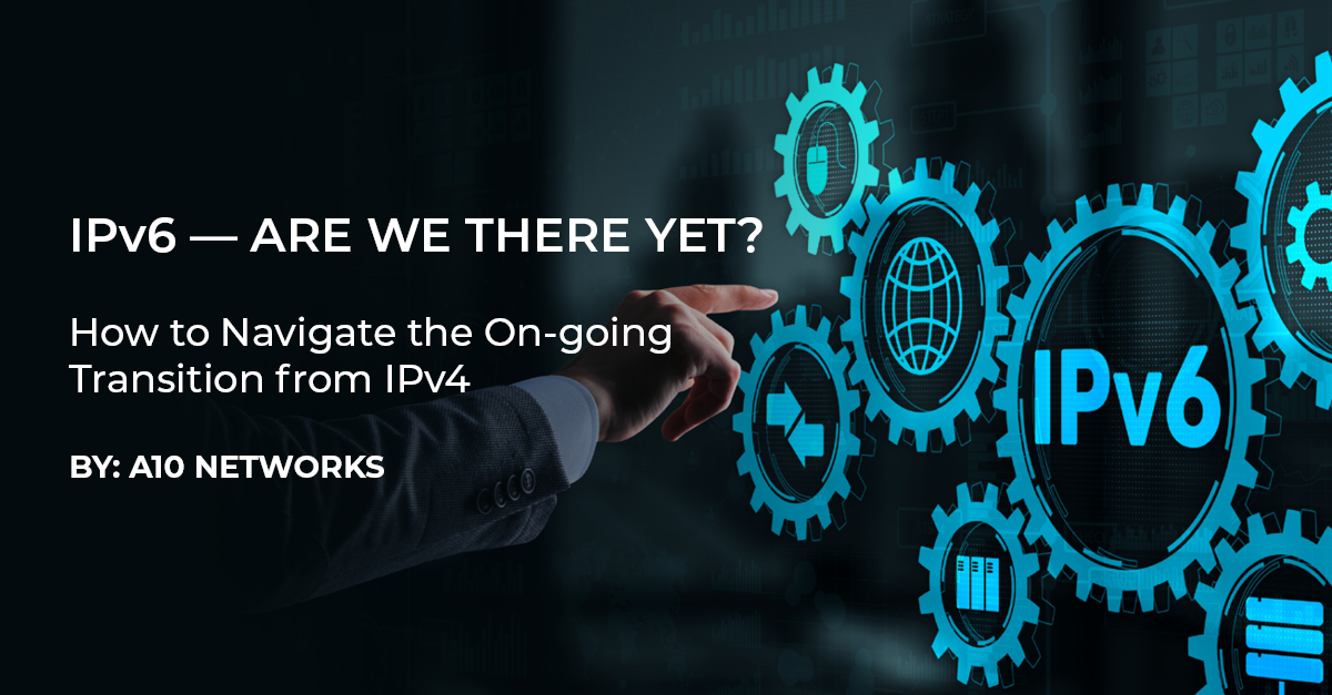
Regional internet service providers (ISPs) including, wireless and wireline/FTTH operators, electric cooperatives and municipalities have long played a vital role in supplying critical power and connectivity to rural and remote communities. Today, 260 telephone and 834 electric cooperatives serve much of rural America1, which includes just 14 percent of the population, but 72 percent of the land area.2 Now these diverse regional ISPs are poised to play a crucial role in connecting the remaining unserved communities and some 23-42 million homes.
 This is a unique opportunity to do far more than just enable unserved communities to catch up to the high-speed broadband taken for granted in densely populated urban areas. By fully leveraging new government funding, increased public interest, and recent digital adoption gains, regional ISPs can help these communities leap ahead in digital adoption, providing them with new capabilities that are absent in high-tech urban areas with older infrastructure.
Digital divide programs like the FCC’s Rural Development Opportunity Fund (RDOF), Emergency Broadband Benefit Program, Connect America Fund, and the USDA’s ReConnect, and more recently the Infrastructure Investment and Jobs Act have made billions of dollars available to help bridge the digital divide. Regional ISPs now have a wealth of opportunities to add subs, build out to new areas, and grow their business. First, though, they’ll need to address the challenges posed by IPv4 exhaustion—and its impact on the cost of new subscriber IP addresses.
Leaping ahead will require a focus on the network end-do-end – not just on the critical last-mile access –but also to the supporting core network technologies and systems that strengthen the overall digital resiliency and security of their network, while meeting rising subscriber expectations. A more comprehensive approach will result in new subscribers served by a network that is fully carriergrade, end-to-end.
One critical core technology that regional ISPs often initially overlook is carrier grade networking – the technology that manages scarce IPv4 addresses and provides a path to IPv6 adoption.
What’s Happening to IPv4?
Every internet-connected home or business requires an IP address. IPv4 addresses, using the original addressing scheme protocol, were fully allocated by the regional IRRs years ago. IPv6, the replacement protocol, provides near limitless address space, but has faced uneven adoption and operational roadblocks. Today, despite 20 years of heavy industry promotion, IPv6 has still not fully replaced IPv4. About two-thirds of subscriber internet sessions and 80 percent of websites are IPv4 only and do not support IPv6.3 In addition, many applications, security devices and other network equipment do not fully support IPv6.
For regional service providers, who must provide connectivity for everyone to everywhere, that means they must support both protocols in their networks for years to come.
IPv4 addresses have become a scarce resource and as a result, the price through private brokers has skyrocketed up to $60 each earlier this year. Large hyperscalers such as AWS, Tencent, Alibaba and others are buying up IPv4 addresses through brokers to create competitive advantage and ensure that their enterprise users of their cloud services always have adequate IPv4 options. AWS, for example, is estimated to control over 100M IPv4 addresses. Organizations, including universities, large corporations, tier one mobile and fixed network operators, and regional service providers, are “selling” their excess IPv4 addresses at market price and using the funds for other infrastructure projects.
The ISP IPv4 Dilemma – Should I stay, or should I go?
The regional ISPs that received an original allocation of “free” IPv4 addresses from ARIN years ago, have built their initial network using IPv4, simply dedicating a public IP to every subscriber/ household served or by using basic NAT to direct IPv6 traffic. Now facing significant subscriber growth through new buildouts, they must make a technology decision to either acquire additional IPv4 addresses at significant cost (but preserving the existing network architecture) or make other fundamental changes in the network architecture to include carrier grade NAT (CGNAT), IPv4-IPv6 transition, and other needed upgrades.
The alternative to IPv4 exhaustion and acquiring more IPv4 addresses is, of course, to use the newer standard, IPv6. IPv4 exhaustion has been an industry topic for over 20 years. Tier 1 service providers that have already addressed the technical complexities through a combination of CGNAT, dual-stack and IPv4-IPv6 transition strategies. However, for smaller ISPs with limited budget, resources and no prior opportunity for significant subscriber growth, the influx of significant government funding may be the first opportunity they have had to reassess and upgrade their core network, including the capacity of their existing IPv4 address pools and a plan to eventually transition to IPv6.
 Often smaller organizations simply cannot justify the near-term cost and disruption that a full network change-out for IPv6 migration will entail. Full IPv6 adoption is costly and time consuming. The IT admin must inventory all connected devices and change out or reconfigure them. There is a risk that a needed device or application will not work and will cause service disruption that will take time to troubleshoot and fix. Older customer equipment may not be compatible with IPv6, and the replacement cost is too high. Balanced against the daily operational demands they face, as well as the need to move forward on strategic initiatives like 5G, cloud, virtualization, edge cloud, and others, administrators may need to delay IPv6 conversion in the short term.
A robust carrier grade networking technology, such as offered by A10 networks can provide an interim solution, by both preserving the limited IPv4 address pools and providing a smooth transition mechanism to IPv6.
What is CGNAT?
Carrier grade NAT (CGNAT), a standard for network address translation (NAT), makes it possible to extend the life of existing IPv4 addresses to support additional subscribers.
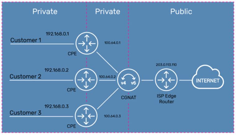
While standard NAT translates a private IPv4 address to public IPv4 address, Carrier Grade NAT (CGNAT) adds an additional translation layer. This allows ISPs to preserve their own public IPv4 addresses, process subscriber traffic through the service provider’s private IPv4 network and support subscribers or businesses that also have their own private IPv4 networks, and multiple locations or devices. Typically, service providers use Carrier Grade NAT (CGNAT) in a NAT 444 scenario, which translates:
The result of a NAT444 (private to private to public) deployment is that it allows multiple customer networks with their own internal network address space to route through the ISP’s internal network address space and share the ISPs single public Internet IPv4 address for access to the Internet. In a residential scenario, NAT444 allows a home router to support multiple home devices and for the ISP to
support multiple home devices or subscribers with a single IP address.
With CGNAT, a single IPv4 address can support multiple endpoints (subscribers/homes). The most common oversubscription ratio is 64:1 for wireline operators but can be even higher. Thus, a single /24 (256 IPv4 addresses) can support 16,384 subscribers or more. If an ISP should decide to “sell” their excess IPv4 addresses, at the peak price of $60 each, one unused /24 block could bring in over $15,000 (minus broker fees). Market prices for IPv4 address vary by region, by block size and other market conditions.
 In 2021, the open market “price” of an IPv4 address in a 256-address block (/24) in North America, jumped from a low of $25 each in January to a high of $60 in late November. The price in the first four months of 2022 has hovered between $50 – $55. What would be the expected price for an ISP looking to acquire more IPv4 addresses to sustain growth in the next few years? Will that high growth in price continue for the next five years or has it now “topped out” and will increase only marginally.
Using CGNAT, regional ISPs can capture new opportunities for growth—while simultaneously positioning their business for IPv6 migration when the time is right. This topic is explored in depth in the eBook, “IPv6 – Are We There Yet? How to Co-exist with IPv4 and IPv6 using CGNAT.”
IPv4-IPv6 Transition Technologies
The IETF introduced IPv6 as a draft standard in December 1998 to solve the IPv4 exhaustion problem and fully ratified it in July 2017. Since its introduction, globally IPv6 adoption has progressively increased across devices, service provider networks, and content providers, but with quite a bit of geographic differences by country.
However, there are still large numbers of websites, devices and networks that are primarily IPv4 and most service providers, education institutions and enterprise must support connectivity between both IPv4 and IPv6 for their users and subscribers, even when their own networks have been fully migrated to IPv6. As a result of this hybrid environment, technologies have emerged that help this transition process and enables connectivity between IPv4 and IPv6 devices, networks, and Internet destinations. These technologies either translate between IPv4 and IPv6 addresses or encapsulate traffic to enable passage through the incompatible network. These technologies include:
These address and protocol translation techniques available allow a subscriber to transparently access content regardless of the protocol stack their device is using, the provider’s access and core network support for IPv4/IPv6, and the destination server support. Tunneling techniques, such as DS-Lite, encapsulate IPv4 packets over an IPv6 access network, while IPv6 Rapid Deployment (6rd) encapsulates IPv6 packets over an IPv4 access network. Native protocol translation techniques, such as NAT64 or NAT46, translate between the protocol stacks at a gateway within the provider’s network when the subscriber and provider networks natively support either IPv4 or IPv6.
 IPv4 and IPv6 will Co-exist for Years Globally, IPv6 adoption will not be achieved overnight. To provide a complete IPv6 service, each link in the chain must be running IPv6, from the end user to the carrier to the content provider. Realistically, not all three of these links in the IPv6
chain will transition to IPv6 at the same time. IPv6 will likely never reach 100 percent adoption. Therefore, most organizations, including communications service providers of all technologies and sizes, will need to support both IPv4 and IPv6 for traffic and subscribers for a long time.
Service providers will need to address upfront the challenges posed by IPv4 exhaustion, IPv6 adoption and IPv6 migration, and its impact on the cost for addition of new subscribers. Service providers need to implement CGNAT wisely — addressing the immediate challenge of IPv4 exhaustion while making plans for an eventual transition to IPv6.
This article was kindly contributed by: Terry Young, Director of Service Provider Networks, A10 Networks
“Storms” are always brewing…
At any moment, your infrastructure can be disrupted by a tree falling, a car accident, or even vandalism. But the costs to your business don’t have to be exacerbated by resource-depleting responses or one-size-doesn’t-quite-fit-all truck rolls. While storm clouds on the horizon may provide some warning, smaller or less obvious issues are much more evasive. How quickly can you locate and assess a problem after your customer reports it? Better yet, can you respond to customer calls by letting them know it is already being addressed? Finally, do you have the ability to accurately determine whether a truck or a team needs to visit the scene?
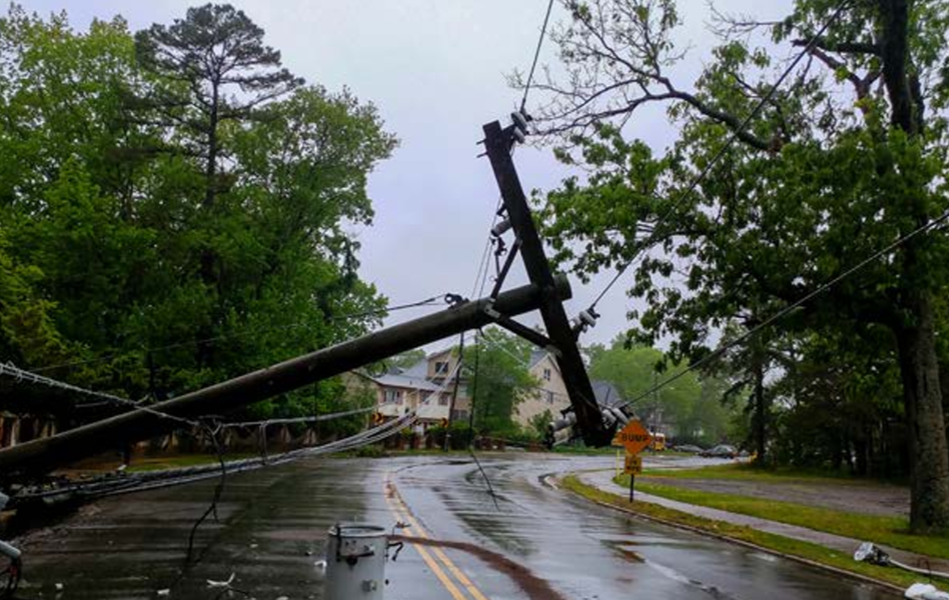 Waiting on customer calls is a 20th-century scenario. Now, you have the power of industry-leading technology — fiber optic technology. And if you’re wondering whether this is only beneficial for internet service providers, think again. Fiber optic technology offers more than fast Wi-Fi. It enables you to monitor your infrastructure end-to-end, be it fiber broadband networks or power grids. Metering and substation technology offer some information, but can you harness all these disparate data points into a unified, holistic view? Most importantly, are you able to recover costs with your current technology?
Revenue-depleting culprits:
A worthy investment
Fiber optic technology like Adtran’s not only empowering operators to modernize and leverage unified insights, but it also ultimately leads to cost recovery and resource protection. Over time, this investment brings quantifiable returns to operators
 Dollar impacts:
Adtran’s fiber monitoring solutions provide comprehensive insights into the health of your grid. While you may already know the power usage and status at your substations, leveraging fiber technology can dramatically enhance your infrastructure view into a more holistic one. Now, you can better manage your grid, your resources, and your revenues.
You have two key advantages… Harnessing your existing expertise and federal grants
You’ve already built a community. For years, you’ve served homes and businesses and held together the foundation of modern society. But beyond lighting your neighborhoods and storefronts, you have the ability to offer your customers reliable internet access. Fiber can help you ensure the reliability of your power grids, but it can also deliver leading internet access and network monitoring.
One of the most important aspects of a fiber build is knowing where it’s needed most. This is your leg up – the blueprints to light up the town, the existing structure of your neighborhoods, campuses, and businesses.
Additionally, there is currently an unprecedented amount of grant funding available to providers nationwide intended to expand communications infrastructure unlike anything seen in decades and unlikely to recur for years to come. With partner programs like Adtran’s, you can receive valuable assistance in the grant application process and maximize the effectiveness of your funding. This presents a unique opportunity to leverage your relationships and expand your resource pool, ultimately leading to an enhanced customer experience and a resilient revenue stream.
You have the power to leverage 21st-century innovation today. With Adtran, you can offer end-to-end services to your community and protect your infrastructure for decades to come.
This article was kindly contributed by Adtran

Broadband service deployment in rural communities has been limited, as it is difficult for legacy providers to justify a business case for broadband in sparsely populated areas. Consequently, the lack of adequate bandwidth for broadband presents a challenge to rural residents— from unreliable work, retail, and entertainment services to unavailable critical healthcare and advanced education services. COVID-19 has only accelerated these trends, cementing high-speed, reliable broadband as an essential service rather than a luxury, no different than other essential utilities that are taken for granted like electricity, gas, or water.
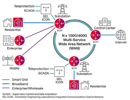
Converged residential broadband/smart grid network for utilities
Rural utilities are in the unique position of having physical infrastructure in place for electric power that can be leveraged to bridge the digital divide. But their core business remains the supply of electrical power, which needs to be delivered more cost-effectively and with fewer staff covering multiple roles. This fuels the need to emulate larger utilities in modernizing their power grid—along with automating their operations and billing—with initiatives such as the deployment of smart meters. The shift towards renewable energy generation, the growth in smart devices in homes, and the expanding electric vehicle ecosystem all create further challenges that place more strain on communications solutions for utilities.
Managing the significantly increased volume of broadband traffic—while allowing critical teleprotection traffic to be prioritized—demands a converged network for both residential broadband and smart grid services that spans both the last mile and the middle mile. This is a key factor when considering investing in a network— can it address the operational challenges of the core utility and deliver rural broadband to the communities it serves.
How is broadband becoming an essential service?
COVID-19 caused a major change in internet consumer patterns. The move to working from home—both for employed adults and students in schools, colleges, or universities— has dramatically increased the use of collaboration applications such as Zoom and Microsoft Teams, causing an exponential growth in internet traffic. And while some schools and offices have reopened, a significant portion of the home-working trend is becoming permanent. The move to remote working and learning, as well as the massive uptick in entertainment streaming services such as Netflix and Hulu, has led to an overnight shift in internet traffic consumption.
Despite the rise in traffic levels, traditional service providers’ metro networks coped well, and connectivity for consumers and businesses in urban areas remains a well-served market. Yet rural areas were already lagging even before COVID-19 in terms of broadband network reach, access speeds, and cost. Despite government incentives, it is difficult for legacy service providers to justify the capital investment across the more dispersed population that characterizes rural broadband. But high-speed broadband is essential for people living in these locations. The need for reliable broadband is now a fundamental part of their working and recreational lives—no different than electricity was over 90 years ago.
The multi-service opportunity for rural utilities
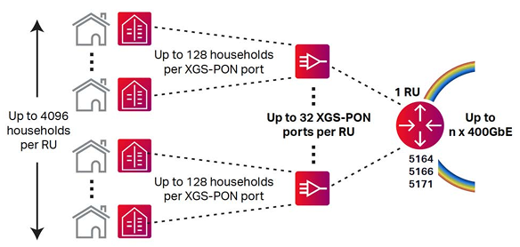
Ciena’s Residential Broadband Solution
Utilities have an existing business justification for investment in high-capacity packet-optical transport between their substations to carry traditional Operational Technology (OT) traffic. Smart grid also impacts a utility’s substation OT services, such as teleprotection for power lines which enables faster and more widespread monitoring and control at substations so the network can respond to failures with corrective action. All the while, the modernized network must continue to support, secure, prioritize, and deliver ultra-low delay connectivity for these essential mission-critical services. It makes sense for utilities to leverage this smart grid infrastructure to aggregate internet traffic from broadband services to meet the needs of their new residential and business customers. Not only does it create a new revenue stream, but also provides an essential service for their rural communities.
Delivering a converged network for smart grid and broadband services
A change of this magnitude in the network—combined with the introduction of completely new service types at the same time—may be viewed as high risk. There are also cultural factors to consider when merging the traditionally separate OT and IT network and teams. This can be mitigated with a plan that divides the transition into three steps.
The first step is to build a middle-mile network to support smart grid traffic. This provides confidence that the solution performance meets the needs of mission-critical teleprotection and other high-volume traffic, such as surveillance cameras and smart meters.
The second step is to offer residential broadband services in rural communities provided through the same network for smart grid. Ciena offers a highly scalable approach that allows utilities to easily go from tens to hundreds of XGS Passive Optical Network (PON) ports without losing sunk platform investments, replacing existing network equipment, or needing significant upfront costs. Ciena’s Universal Aggregation (UA) and access capabilities support multiple service options in addition to XGSPON.
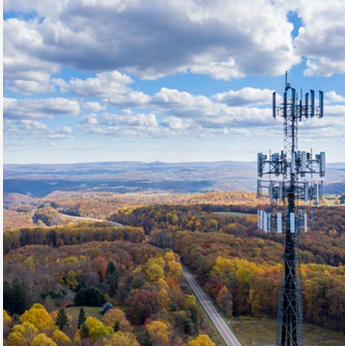 The final step is to offer wholesale and business connectivity services. For example, in regions with 5G rollout in progress, mobile carriers will be looking for a significant amount of additional capacity. In both the business and public sectors, there are opportunities for capacity to support business applications, telemedicine, or remote learning.
With this solution modularity, utilities can offer enterprise business services over IP or dedicated Ethernet and mobile wholesale services with xHaul transport capabilities. Moreover, they can have a highly-optimized footprint that reduces energy and space requirements to sustainably expand addressable market and revenue opportunities. Hardened and weatherproof platforms provide utilities with maximum flexibility and the ability to move their Optical Line Terminals (OLTs) closer to end-users for improved performance. This solution leverages the power of Ciena’s portfolio, including Routing and Switching platforms with XGS-PON pluggable technology, market-leading optical networking technology, Ciena’s Manage, Control and Plan (MCP) domain controller, Blue Planet® Intelligent Automation Software, and Ciena Services.
Broadband beyond the network elements
Utilities are looking to deliver the best Quality of Experience (QoE) to their customers while increasing operational efficiencies. As networks have grown, broadband network planning, infrastructure commissioning, service fulfillment, and service assurance can be complex. Ciena’s PON Operations, Administration, and Maintenance (OAM) software simplifies network and service management. PON OAM can be cost-effectively hosted on an external x86 server or internally on Ciena’s Universal Aggregation platforms as part of WebGUI.
Ciena’s Residential Broadband Solution also leverages Ciena’s MCP domain controller. This allows utilities to scale the network, simplify operations, reduce cost, and deliver the agility and resiliency their customers expect. It provides utilities the ability to manage and orchestrate their multi-layer network from end to end—including middle mile, last mile, and Customer Premises Equipment (CPE)—when delivering broadband, enterprise, or mobile wholesale services using a common and integrated platform.
Full support to new and existing utilities
As many utilities may not necessarily be set up to execute complex IT deployments, Ciena Services’ extensive experience, processes, and economies of scale can help assure a successful rollout. Depending on needs, Ciena Services is ready to assist—from initial planning and design, systems integration, and implementation to ‘Day 2’ services to optimize, support, and manage this powerful solution. Ciena Services also offers an extensive library of learning courses and labs to grow IT teams’ residential broadband knowledge. Ciena’s services are designed to be flexible—they are available individually or as a packaged solution—and consist of Consulting, Implementation, Systems Integration, Maintenance, Managed Services, Optimization, and Learning.
Ciena’s solution also includes the Ciena Partner Network’s Marketing as a Service program (MaaS)—an award-winning marketing service that takes network operators to market faster with collaborative engagement, execution, and dedicated marketing experts to accelerate time to revenue. Ciena not only supports the development of go-to-market strategies, but also executes to win business together.
Utilities are moving away from legacy chassis-based approaches because they simply do not offer the capacity, efficiency, or adaptability required to succeed in a highly competitive market while supporting new and emerging application requirements. Ciena leverages innovative broadband architecture and proven expertise in deploying ultra-high-capacity networks to thrive in the growing residential broadband market.
Sustainability cannot be an afterthought
 Investing in infrastructure to close the digital divide without considering all relevant environmental and economic sustainability aspects can negatively impact any service provider’s long-term financial viability.
At Ciena, we continue to invest in the sustainability of all critical network elements by converging the access infrastructure with best-in-class routers, WaveLogic™ coherent optics, and innovative uOLTs and corresponding ONUs. Sustainability models show we have already helped our customers avoid more than 550,000 metric tons of CO2e over an eight-year period (2014–2021) with our Routing and Switching Platforms—helping our customers’ production networks achieve 23 percent savings in power consumption, equaling 96,000,000 kWh saved which resulted in $12 million per year OPEX savings.
Through our WaveLogic coherent optic investments, we introduced the industry’s first 400 Gb/s transceiver in 2017 and are delivering the pluggable version five years later at one fifth the power, one tenth the space, and with improved industry-leading systems performance.
Combining Ciena’s routing, optical, and PON innovations together offers significant improvements in footprint and power savings to enable more efficient and sustainable networks for our customers—and the planet at large. For example, evolving from a traditional pure PON chassis-based, multi-boxed solution to Ciena’s converged access with XGS-PON and routing in a single platform results in a 67 percent reduction in footprint and 63 percent reduction in power consumption. This is just one example and, when applied to 100,000 homes passed at 50 percent market share (12 sites) using a 64 OLT split, can avoid 84,400 kWh annually, resulting in 59.8 metric tons of CO2e avoided. A higher market share rate or homes passed would yield much larger sustainability results. To quantify the value of Ciena’s sustainable approach to broadband, we have partnered with ACG to develop an online business case tool that can quantify the TCO advantages of Ciena’s broadband architecture vs legacy chassis-based and closed pizza box approaches. Our subject matter experts will work with the customer to analyze their planned rollouts and develop both a 5-year TCO and ROI analysis tailored to the customer’s network needs.
We welcome utilities that are in their planning stages for broadband to reach out to us to take advantage of these on-line business case tools to aid them in their broadband journey.
This article was kindly contributed by Ciena
 Cooperatives brought electricity and telephone services to rural households nearly a century ago. Today, rural electric cooperatives are ideally positioned to deliver affordable, high-speed broadband to their members. By leveraging federal funding, rural electric cooperatives are taking an increasingly active role in closing the digital divide and ultimately improving access to education, healthcare, and economic opportunities for the communities they serve. At the same time, cooperatives can modernize their operational networks to deliver reliable power at a lower cost.
This article provides insights into a proven success model that addresses both critical challenges simultaneously, along with practical steps that rural electric cooperatives can take to get started.
The Broadband Opportunity
Thirty-five percent of rural Americans lack access to minimally acceptable broadband speeds, according to the White House. Dial-up and DSL just don’t cut it anymore.
Inadequate Internet access was on full display during the pandemic. The FCC estimates that 17 million schoolchildren lacked Internet access. As schools across the nation shifted to remote learning to protect the health and safety of students and teachers, children in Internet deserts were forced to Zoom into their classes from fast-food restaurants or struggle with bandwidth constricted mobile hotspots.
Even before the pandemic, the federal government has been actively working to bridge the gap. Through the Rural Digital Opportunity Fund (RDOF), the FCC is directing up to $20.4 billion over 10 years to finance up to gigabit speed broadband in unserved areas. Millions of American homes and businesses will be connected with digital opportunities for the first time.
Brain drain has also been a longstanding concern in rural areas, as educated workers seek opportunities in metropolitan areas. High-speed broadband can not only keep young people in their communities but attract new people to rural areas and small towns.
As a reaction to the pandemic, families are trading city life for the open spaces and natural beauty. But they expect high-quality broadband when they get there, and in fact, their ability to continue to work remotely depends on it. An influx of high wage workers and their families can fuel growth, business activity, and build vibrant communities.
Expanding access to highspeed broadband can have a positive impact on rural electric cooperatives themselves. Without a compelling broadband offering, cooperatives risk member attrition, which impacts not only the organization itself but its anchor members—the schools, healthcare providers, government, public safety, and local businesses that also serve their communities. Affordable, multigigabit connectivity is essential for these organizations to serve their customers and constituents.
Building a Network for a Modern Grid
Rural electric cooperatives can address their communities’ need for affordable, high-speed broadband while also leveraging a shared fiber network that supports smart grid applications and their operational technology (OT) needs. Legacy telecom networks simply won’t support the next-generation applications that can increase grid performance, increase service reliability, and lower costs for coops.
Power grid dynamics, such as distributed energy resources, smart grid initiatives, and delivery of new services can have a profound effect on network requirements. Realizing the vision of a dynamic and stable grid requires a highly available, service- provider-grade network that supports grid applications today and in the future. The network must seamlessly interconnect with energy producers and transmission grids and enable the delivery of advanced power services to members.
Modernizing the grid network will also help rural electric cooperatives increase cybersecurity and meet North American Electric Reliability Corporation (NERC) compliance. Cybersecurity is increasingly critical as utilities deal with more regulation, cyberattack frequency, and the threat of state-sponsored attacks on critical infrastructure.
A Vision for Community Development
Juniper Networks has teamed with industry professionals and partners with more than 20 years of knowledge to develop a proven success model for rural electric cooperatives.
Working together, our objective is to help rural electric cooperatives understand the financial feasibility and develop an effective strategy to deploy an optical fiber network to support the grid, while creating an infrastructure asset that connects anchor members in an optimized, scalable way. Communities within a co-op’s service area will see economic benefits, such as job creation, training, placement, and community development.
Some cooperatives begin their broadband journey with fiber-tothe-home projects for residential members. Some of these projects have been successful, but this starting point injects a higher risk, negates potential funding operations, and misses out on economies of scale. This approach can also disquiet residential members due to implementation priority, and it typically misses the benefit yields captured when the high-speed connectivity needs of the entire cooperative service area and anchor members are considered.
At Juniper, we believe a strategic approach that simultaneously addresses the network challenges of the power grid and lays the foundation for high-speed broadband throughout a cooperative’s service area will deliver lower risk and a higher value-to-cost ratio.
We have observed that a focus on delivering broadband services first to anchor members, followed by the extension of broadband into residential areas, has greater success. A fiber network that’s engineered to meet the needs of anchor members in education, healthcare, public safety, local government, and business, creates a stronger foundation for community and economic development.
Six Principles for Success
At Juniper, we recommend rural electric cooperatives follow six success principles when developing a strategy to simultaneously address the network challenges of the power grid and lay the foundation for broadband throughout the service area. These success factors lower risk and deliver a higher value-to cost ratio.
1. Shift from microwave to fiber connectivity
A fiber network that is properly engineered for a cooperative’s service area will create an investment asset with a more flexible business model. Benefits include improved grid reliability, lower operational costs, increased cybersecurity, advanced interconnection to power providers, and a host of next- generation services for anchor members.
This flexibility allows cooperatives to choose the business model that best serves their members.
Once a fiber infrastructure is in place, the wireless systems previously in operation, such as point-to-point terrestrial microwave, can be repurposed to support lower bandwidth applications.
2. Assess the potential for services
A modern IP network lays the foundation for a broad range of services for both rural electric cooperatives and their anchor members.
Rural electric cooperatives can leverage a modern IP network to accommodate current and future IT/business or OT/grid applications, including advanced metering infrastructure (AMI), distribution management system (DMS), outage management system (OMS), emergency management system (EMS), and teleprotection.
A modern fiber network supports substation video surveillance, facilities management, smart grid, supervisory control and data acquisition (SCADA), Industrial Internet of Things (IIoT) systems, and industrial cloud applications. Integrating cybersecurity into the network infrastructure strengthens protection and simplifies NERC compliance.
The benefits of high-speed broadband and smart grid are wide-ranging for the community at large:
 Telemedicine makes care readily available with services that include telepsychiatry, tele-stroke, electronic intensive care unit (eICU), and prenatal care for high-risk pregnancies. High-speed connectivity enables expedited reading of X-rays and other medical scans as well as an exchange of electronic health records to deliver better patient outcomes.
3. Build a connectivity hub for “on-ramp” to high-speed connectivity
Designing the fiber network for the service area with a central access point creates an on ramp to applications that will ultimately fill that fiber connection with value-added and revenue generating services. Building a connectivity hub ultimately drives down the access cost for members and creates a seamless, secure access point for subscriber-based service providers and cloud applications.
A connectivity hub, which is essentially a small data center, creates an efficient on-ramp to the Internet and serves as a secure access point for service providers and users of cloud services. Designing the connectivity hub is an essential part of the assessment, design, and build phases for the service area. This hub can also serve as a cost-effective disaster recovery point between adjacent cooperatives that adopt this model.
4. Tap into available funding
The initial assessment and design phases of the fiber network should consider how to leverage public funding. Tapping into funding vehicles can accelerate service delivery when anchor members are identified, especially in education and healthcare.
Cooperatives should consider funding vehicles, including E-Rate Category 1, which includes the services needed to support broadband connectivity to schools and libraries.
The first phase of Rural Digital Opportunity Fund (RDOF) will target 6 million homes and businesses in census blocks that are entirely unserved by voice and broadband speeds of at least 25 Mbps/4 Mbps. Subsequent phases will cover locations that are partially served.
5. Consider the options for service delivery
Implementing a fiber network and on-ramp connectivity hub is foundational to the success of offering broadband and modernizing the grid network. Crafting a services delivery strategy that balances the long-term goals of the cooperatives, maximizes partnerships, and leverages local providers will yield the highest value for electric cooperatives as well as their residential and anchor members.
6. Develop a strategy for your service area
This article was kindly contributed by Juniper Networks

Fiber is the driving force of the broadband connectivity today. It is the biggest and fastest growing fixed access technology with the largest eco-system of players that includes fixed and converged operators, governments, cities, utilities, enterprises, and infrastructure investors. Fiber broadband investment is attractive because it enables a premium customer experience, competitive advantage, the lowest operational costs (OPEX), and the lowest power consumption of any broadband technology, with the additional opportunity of service convergence (residential, enterprise and 5G transport).
One of the greatest attributes of fiber is unlimited bandwidth potential. As technology evolves, the same fiber networks will be able to increase capacity using the same fiber infrastructure, without the need to make updates in the most valuable part of the network: the fiber outside plant.
The increase of capacity is possible by adding new wavelengths (or colors of light), each wavelength carrying data traffic and even working on different transmission rates. New fiber technologies unlock the potential of fiber to be a single infrastructure that underpins the entire telecom ecosystem and connect everything and everyone: consumers, businesses and even 5G cell sites.
Today, fiber networks are based on Gigabit PON (GPON). The next step is XGS-PON which reuses the same outside fiber plant (fiber cables, splitters, and access nodes) to increase bitrates to 10 Gb/s. The industry is already working on further evolutions beyond 10 Gb/s. The next generation of PON technologies are essential to meet ever-growing bandwidth demand and ensure that the fiber networks built out today can be used for decades to come.
This article examines the future PON fiber technologies beyond 10 Gb/s.
The history of PON and the new paradigm
Previous generations of PON technology have derived their origins from long-haul optical technologies. After these technologies were adopted by the metro market, they drove component volumes and maturation further and eventually reached a price point that became viable in a massivescale fixed access deployment. These technologies have had to be adapted for larger power budgets and the burst mode operation used in PON. Nevertheless, the trickle-down process has worked well, spawning EPON, GPON and 10G PON technologies.
The future generations of PON will use a slightly different, but highly efficient path. They will be based on the world of data centers and, specifically, 100G Ethernet technologies with 25 Gb/s channels that are used for intradata center connectivity.
The increased demand for data center capacity, much of it on single-mode fiber, has begun to drive large volumes and reduced costs on 25G components. This is the mature ecosystem that the next generation of PON leverages, and 25 Gb/s will be the baseline for the next steps: 25G, 50G and 100G PON.
Is it possible to just plug these data center components into OLT and ONU transceivers? Of course not. PON applications will require new wavelengths, a higher launch power from transmitters, and greater sensitivity from receivers. However, this is no different from the work that has been done for previous PON generations based on components from long-haul and metro transceivers.
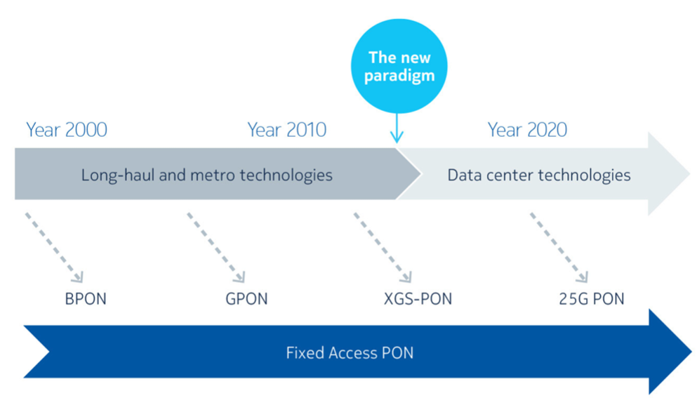
PON evolution depends on the pre-existence of mature optical and electronic technologies. 25G PON leverages mature Data Center optical technologies.
25G PON: the best next step
For an access technology to be successful, a few significant requirements need to be fulfilled. The first is cost efficiency, which includes CAPEX and cost of introduction, etc. In massive access networks deployments, where millions need to be connected, cost-efficiency is key. There are examples of technologies that have a very attractive value proposition but, because of complexity and a very high cost, they did not become widely adopted. Next, there must be well-defined, viable use cases in the near- and mid-term for the technology. 25G PON fulfils these conditions.
Cost efficiency
25G will be the most cost-effective evolutionary step for the next decade. It leverages mature and massively deployed data center technologies. It is a simple technology which does not require advanced digital signal processing (DSP), amplifiers or tunable lasers. 25G PON is likely to be the last step in the evolution that will be a straight evolution from 10G PON: steps beyond 25G will be a technology leap and require advanced DSP and optical amplifiers or even coherent, all of which will take years to mature.
Use cases
The massive capacity of 25G PON will enable unified services—connecting everyone and everything over a single highperformance network. Operators are already seeing the demand for speeds beyond 10 Gb/s to:
Huge capacity
25G PON is 10x faster than GPON and 2.5x faster than XGS-PON. The Ethernet market has found that a step increase in speed by a factor of 2-2.5x delivers the best commercial results. The 25G step has been adopted by IEEE (25G EPON), data centers, WDM, G.metro and 25GS-PON MSA. It is driven by concrete demand for enterprise services and 5G transport and will be able to meet residential demands when the time comes. To illustrate: today, 1 Gigabit is a product for premium connectivity in many markets, and 25G (when overheads are accounted for) is 20x faster. That should be enough bandwidth for at least the next decade.
Simple introduction
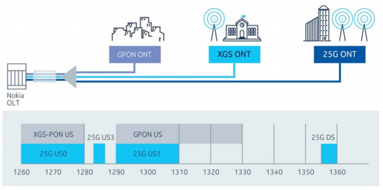
25G PON wavelength plan ensures triple co-existence (GPON, XGS-PON and 25G PON)
Co-existence is a major requirement for ensuring graceful migration and avoiding complicated (and costly) operations. Network upgrades don’t happen overnight, they are done gradually, so old and new technologies will need to co-exist for many years. By the time upgrades to >10G are needed, most networks will have both GPON and XGS-PON in the field.
One of the great attributes of 25G PON is that it can seamlessly co-exist with both GPON and XGS-PON, so there can be three generations of PON on the same fiber infrastructure, which enables operators to use the right technology and speeds for each service. There are no forced migrations, no restrictions, and no overlay deployments.
Availability
Operators are already seeing the need for capacity beyond 10 Gb/s and 25G PON is available today. Operators will be able to react quickly when needed and protect their business. Waiting for a new technology—and losing opportunities in the meantime—is not an option.
This is why 25G PON is so important. It is available today, has huge capacity and is very easy to introduce. 25G PON was already introduced in a live network.
25G PON implementation
The guiding principle of 25G PON is to deliver 2.5x more bandwidth at <2.5 higher cost. The strategy to lower the incremental cost is composed of the following elements:
The 25G-PON standard specifies 1358 nm wavelength in downstream and three options for upstream:
This choice of wavelength plan ensures a smooth evolution path in any network.
The path to 50G PON
 The standardization work on 50G PON G.hsp (Higher Speed PON) is already under way and Nokia is one of the main contributors to the ITU-T standardization work. The evolution to 50G PON is a long-term evolution, and it is more of a quantum leap than an evolution. Running at such high speeds has several engineering challenges. Tweaks to address these challenges increase the complexity and cost, and time to mature.
50G PON will be able to use some 25G components but not everything. It will need new, more costly 50 Gb/s transmitters and amplifiers (EML+SOA). This is because when a 25 Gb/s transmitter tries to transmit at 50 Gb/s, the signal is distorted. To compensate, 25G transmitters will need to be used in combination with optical amplifiers. The alternative is to use 50G transmitters. In both cases, the cost is higher.
50G PON can leverage 25G optical components in receivers, but it will need advanced DSP to be able to achieve 50 Gb/s bitrates with 25 Gb/s optics. This adds significant cost. In fact, that will be the case with all technologies beyond 25G PON. To bring the cost down, DSP must be integrated in SoC (system on chip) and reach high volumes, which will take time. It is expected that 50G will not take off in the next 7-8 years. This also means there will not be mass volumes before 2030 to drive down the cost. None of this is an issue for 25G PON.
50G PON will require optical amplifiers for all loss budgets. For higher speeds, there is a higher power penalty at the receiver so, to compensate, 50G PON needs to launch at a higher power at the transmitter.
Although Nokia Bell Labs has had a 50G PON demo for some time, and early industry prototypes are being available, it does not mean that 50G will be deployable soon. There is a need for further research work to optimize the technology. For example, the practicality of high loss budgets (>29 dB) is still to be determined. The symmetrical bandwidth is still under evaluation (note that the 50G standardization deferred the specification for 50G in upstream because of its complexity and has standardized 12.5Gb/s and 25Gb/s in upstream).
Another challenge of 50G PON is the co-existence with other technologies. The current specification enables co-existence with GPON or XGS-PON but not both at the same time. Consequently, operators who want to introduce 50G PON in their networks must either decommission their GPON network first and move all customers to XGS-PON, or skip the XGS-PON step and upgrade GPON to 50G PON directly. This clearly complicates the evolution path, which is not the case with 25G PON, as it can co-exist with GPON, XGS-PON and even 50G PON simultaneously on the same PON.
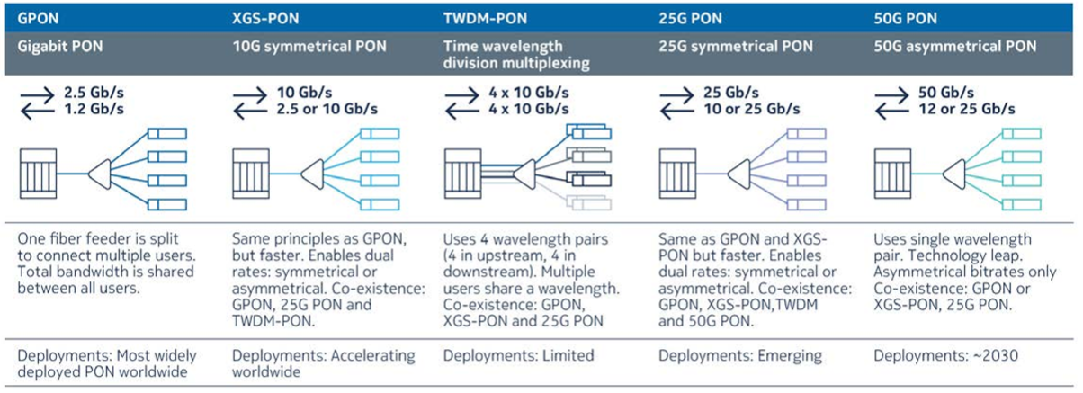
Overview of TDM PON technologies
The futuristic 100G PON and beyond
Nokia Bell Labs recently showed the industry’s first 100G PON demo. Bell Labs leveraged the same base technology that is needed for 50G PON using advanced DSP techniques that are not yet commercially available. Once there is a baseline ecosystem for 50G PON, the step to 100G PON will follow quickly.
The Bell Labs demo also demonstrated Flexible Data Rates, which is an industry-first in PON networks. Flexible rate transmission groups ONUs that exhibit similar physical network characteristics (e.g., located at around the same distance from the OLT, with similar loss or dispersion). ONU groups benefit from dedicated, optimized performance e.g., more efficient data transmission, lower latency, and lower power consumption. Note that Flexible Data Rates is not a feature that is directly linked to 100G PON; it could be implemented for any PON technology.
The higher speed of 100G PON brings a power penalty at the receiver. In 50G PON, this problem can be solved by a higher launch power at the transmitter. However, for 100G PON this is not a practical approach, and more advanced solution for the receiver must be found.
To fulfill a 29 dB and 32 dB loss budget, 100G TDMPON will probably require a coherent receiver. For symmetrical 100G, a coherent burst mode receiver will be required, and this is an active area of research. There are at least three possible scenarios that could lead to a practical 100G coherent PON in the second half of the next decade:
Regardless, the PON industry has a few years before needing to make technology decisions about 100G PON.
Once coherent technology proves-in for TDM PON, the sky is the limit. 400G coherent is already deployed today in core, metro and lately DCI networks, and commercial systems supporting more than 400G are emerging.
 Conclusion
It is important to keep pushing the boundaries of PON technology and make sure the investments in fiber networks made today will be usable for many years to come to meet the inevitable growth in demand for faster, more responsive, and immersive internet services.
The industry is already embracing 25G PON and the research work on 50G and 100G PON is ongoing. Nokia is leading the industry, with the first 25G PON commercial solution that has been deployed in a live network. We are one of the main contributors to the ITU-T 50G PON standard. In early 2021, we demonstrated the industry’s first 100G PON prototype.
However, 50G PON and 100G PON are still far from being deployable. They require more research, development of a new generation of lasers, optical amplifiers and DSPs, and further optimization to reach maturity and an acceptable cost point. These advances in technology will ensure the evolution of fiber networks and demonstrate the superiority of fiber to serve as a unified infrastructure to connect everything, everywhere.
This article was kindly contributed by Nokia
A Historical Investment in Fiber
The power of fiber to help local communities grow is immense. But let’s start with why now is the right time to get into fiber in the first place.
There has never been a better opportunity for utilities, telecommunications providers, and governmental institutions to make an investment in new fiber networks. Why? We live in an era of unprecedented investment in expanding and enhancing broadband networks across the United States. Here’s a snapshot of the recent funding available through federal and state governments:
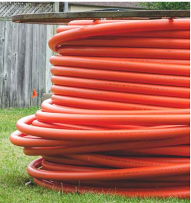 The American Rescue Plan Act of 2021 allocated $350 billion to state, local, and Tribal governments. Billions of American Rescue Plan dollars have already been awarded toward broadband infrastructure projects. In January 2022, the Treasury Department expanded the funding rules to allow for more broadband projects.
What Fiber Can Do for Communities
 Why fiber, and what will it do for your community? Fiber is uniquely positioned to power economic development and here’s why:
Communities in which fiber networks are built almost instantly have access to innumerable opportunities that a fiber connection provides. For example:
These examples merely scratch the surface. But what can research and existing fiber deployments tell us about the true power of fiber? Read on.
Real-World Examples and Statistics
When it comes to the power of fiber to promote a community’s economy, the data is clear and offers proof behind the theory. Here are just a few remarkable real-world examples:
 Fiber increases local business revenue. Earlier this year, an RVA Market Research & Consulting study concluded that “over $78 million per year of additional primary revenue from home-based businesses could be gained from an FTTH community of 100,000 households.” This study also showed that, for home-based businesses on a fiber connection, income from outside the community was 73% higher than it was for home based businesses on a different kind of connection.
As more Americans have access to fiber networks, statistics and stories like these will become the norm.
Conclusion
Fiber broadband is a driver of economic growth for communities small and large, urban and rural. The potential growth afforded by fiber is good news for every community in the country, and there has never been a better time to lead the way toward—and find the funding for—fiber broadband deployment.
This article was kindly contributed by Corning Optical Communications
Using the right splitter is important!
Manufacturers make many different types of indoor splitters depending on the application. As well, housings also vary depending on the intended use.
Some indoor splitters are digital-rated for use with high output modems, some have different case sealings such as solder back or epoxy back plates and some have surge protectors.
When designing and building a new facility or machine, engineers need to fully understand the specifications – the strengths and weaknesses of each wire available for the job. The biggest challenge for an engineer is to balance the best wire for the project and the budget.
THHN / THWN / THWN-2 and XHHW / XHHW-2 – are a lot of letters to understand, but they are two common types of building wire, and it’s critical to understand the differences between the two in order to choose the best wire for your application.
Below is a simple chart comparing some of the specifications, and differences:
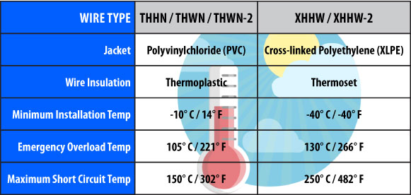
As you can see, XHHW-2 has a much higher tolerance for heat – an important factor to consider.
| THHN | THWN | THWN-2 |
| T = Thermoplastic HH = High Heat Resistance N = Nylon Coated Temp Rating: 90° C in dry locations |
T = Thermoplastic H = Heat and W = Water Resistance N = Nylon Coated Temp Rating: 90° C in dry locations and 75° C in wet locations |
T = Thermoplastic H = Heat and W = Water Resistance N = Nylon Coated Temp Rating: 90° C in both dry and wet locations |
The most popular type of building wire used in construction is Thermoplastic High Heat-resistant Nylon coated (THHN) wire. THHN wire is also commonly used in machine tools, control circuits and some appliances.
THHN wire comes in a variety of characteristics:
Aside from the mechanical protection, a nylon jacket protects the wire from abrasion as it’s pulled through conduit. In addition, the jacket protects the wire from hydrocarbons such as oil, gasoline and grease. The tough nylon jacket also protects the wire from being puncture or accidentally cut as it protects the insulation.
THHN wire is approved for up to 600V and is listed by Underwriters Laboratory (UL), as rated for 90° C (194° F) in dry and 75° C (167° F) in wet environments. THHN wire comes with a dual rating: THHN / THWN, which means it’s appropriate for both dry and wet applications.
| XHHW | XHHW-2 |
| X = Cross-Linked Polyethylene (XLPE) HH = High Heat-Resistance W = Water Resistance Temp Rating: 90° C in dry locations and 75° C in wet locations |
X = Cross-Linked Polyethylene (XLPE) HH = High Heat-Resistance W = Water Resistance Temp Rating: 90° C in both dry and wet locations |
XHHW-2 wire is the next generation XHHW wire. While its main use is for residential, commercial and industrial buildings, it is also used in raceways, feeder and circuit wiring.
XHHW-2 is approved for use up to 600V and is UL Listed for 90° C (194° F), in both dry and wet locations. The previous generation of XHHW had a lower temperature rating, approved up to 75° C in wet environments, making the next generation XHHW-2 wire a more useful and an ‘all environment’-type product.
Wire and Jacket Insulation:
In addition to the specifications noted above, the main difference between THHN / THWN / THWN-2 and XHHW / XHHW-2 and is in the wire’s jacket. The jacket on the THHN family is thinner – this means that while more THHN can be fit through many obstacles, its jacket doesn’t offer as much protection as the XHHW jacket. As well, the coating on the XHHW’s jacket is more resistant to chemicals, ozone and abrasions while THHN’s thinner coating, under extreme conditions, can lead to current leakage and can break down from chemical or environmental exposure, emitting a toxic smoke when burned.
Flexibility:
Surprisingly, even though XHHW has a thicker and more protective jacket, it is also more flexible than THHN wire. This is due to the XLPE insulation of the XHHW allowing the cable to bend and flex more easily than the PVC insulation of the THHN – making XHHW much easier to work with during the installation process.
Final Thoughts:
As always, the decision between using THHN or XHHW comes down to weighing performance versus budget. Our customers often express that the more popular and less expensive THHN wire is perfectly suitable for what they need. On the other hand, XHHW has the additional features that provide increased efficiency and extended longevity.
Also see: RHW, RHW-2, USE-2 and RHH Building Wire – Explained
Fast Ethernet refers to an Ethernet network that can transfer data at a rate of 100 Mbit/s. It can be based on a twisted pair or fiber optic cable. (The older 10 Mbit/s Ethernet is still installed and used, but such networks do not provide the necessary bandwidth for some network video applications.)
Most devices that are connected to a network, such as a laptop or a network camera, are equipped with a 100BASE-TX/10BASE-T Ethernet interface, most commonly called a 10/100 interface, which supports both 10 Mbit/s and Fast Ethernet. The type of twisted pair cable that supports Fast Ethernet is called a Cat-5 cable.
Gigabit Ethernet, which can also be based on a twisted pair or fiber optic cable, delivers a data rate of 1,000 Mbit/s (1 Gbit/s) and is becoming very popular. It is expected to soon replace Fast Ethernet as the de facto standard.
The type of twisted pair cable that supports Gigabit Ethernet is a Cat-5e cable, where all four pairs of twisted wires in the cable are used to achieve the high data rates. Cat-5e or higher cable categories are recommended for network video systems. Most interfaces are backwards compatible with 10 and 100 Mbit/s Ethernet and are commonly called 10/100/1000 interfaces.
For transmission over longer distances, fiber cables such as 1000BASE-SX (up to 550 m/1,639 ft.) and 1000BASE-LX (up to 550 m with multimode optical fibers and 5,000 m with single-mode fibers) can be used.
10 Gigabit Ethernet is the latest generation and delivers a data rate of 10 Gbit/s (10,000 Mbit/s), and a fiber optic or twisted pair cable can be used. 10GBASE-LX4, 10GBASE-ER and 10GBASE-SR based on an optical fiber cable can be used to bridge distances of up to 10,000 m (6.2 miles). With a twisted pair solution, a very high quality cable (Cat-6a or Cat-7) is required. 10 Gbit/s Ethernet is mainly used for backbones in high-end applications that require high data rates.
The “Internet of Things” (IoT) is becoming the hot topic of conversation both in the workplace and outside of it. It’s a new and exciting concept that not only has the potential to impact how we live but also how we work.
Let’s start with understanding a few things: We all know that broadband Internet is amazing in so many ways and is become more widely available to everyone worldwide. The cost of connecting to the Internet is decreasing, more devices are being created with Wi-Fi capabilities, technology costs are coming down, and who doesn’t have a smartphone these days? All of these are the ingredients of an Internet of Things perfect storm.
 So What Is The Internet Of Things?
Simply put, this is the concept of connecting any device with an on/off switch to the Internet – and to each other. This includes everything from your house lights and fans, smartphones, coffee makers, computers, washing machines, vehicles, wearable devices and almost anything else you can think of.
As mentioned, if it has an on/off switch then chances are it can be a part of the IoT. It is predicted that by the year 2020 there will be over 100 billion connected devices – and growing exponentially. The IoT is quickly becoming a giant network of connected “things” – and remember, people are things too. The IoT interconnectivity will be between people and people, people and things, and things and things. With an on/off switch and the right components there is nothing that cannot be connected to the IoT.
What if your in-home IoT system switches on your energy efficient hot water heater at 6am when your alarm clock is set for 6.30am, and then notifies your coffee maker to start brewing coffee for you? What if your car knew exactly where you are going, detects that traffic is heavy and reroutes you while factoring in that you need fuel, and sends a text message to your boss that you are running late and included an estimated ETA?
Here’s the new rule: Anything that can be connected, will be connected
It’s not hard to see how and why the IoT is becoming such a hot topic today – it opens the door to limitless opportunities, but also to many challenges – with the biggest challenge being security. With billions of devices connected together, will someone be able to hack into your child’s ‘smart doll’ and gain access to your entire network? But that’s a subject for another day…
The topic of the benefits of the IoT is taking place all over the world right now – companies are inventing new devices specifically to take advantage of this convergence of the communication of things – and how this will impact our lives. It’s critical that we look at our business models and ask ourselves how we fit into this wave of IoT and how we can take advantage of it. The IoT is where this world is going – and you’re a part of it whether you want to be or not – because you know, you’re a thing too.
Whether it’s through your personal phone, wearable tech or everyday household objects, IoT will connect us in ways we can’t even imagine yet. So, if you are like Multicom and are looking to hitch your wagon to a rising tide, grab the coat-tails of the coming IoT standards tidal wave and hang on for the ride of your life.
Multicom has been connecting things since 1982, and will continue to ride the wave of IoT, fiber optics and other technologies into the future. The communications industry is changing at the speed of light and someone has to lock-on to latest innovations. The products that go into video, WiFi, data and voice signal distribution are advanced, ingenious and constantly being reinvented. If you’re not an innovator, you’ll get left behind.
How do we keep up? How do we make it easier for our customers? At Multicom we accelerate the transition of emergent products – we manufacture reliable and cost-efficient products, and our informed staff are trained to be on the top of their game – always. This is essential for our customer’s success and the future of the industry.
Up next… The Industrial Internet of Things (IIoT)
For several years, the optical fiber user community has been rapidly shifting from traditional singlemode fibers to new “Full Spectrum” singlemode fiber that meets the International Telecommunications Union (ITU-T) G.652D specification.
First off, these terms are important:
G.652 singlemode fiber, also known as standard single fiber, is the most commonly deployed singlemode fiber. It has four variations: G.652A, B, C, and D – and two classifications. The first classification is G.652.A and G.652.B fibers, these are designed to have a zero-dispersion wavelength near 1310nm and are optimized for operation in the 1310nm band. However, they are not suitable for applications in Wavelength Division Multiplexing (WDM) due to water peak. The more advanced classification of G.652.C and G.652.D fibers are optimized with a reduced water peak for spectrum operation, which allows them to be utilized in the wavelength region between 1310nm and 1550nm to support Coarse Wavelength Division Multiplexed (CWDM) transmission.
Comparing Conventional G.652.A/B with LWP fiber and ZWP fiber:
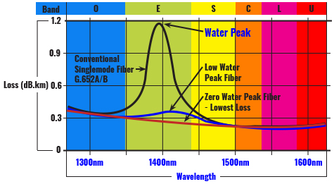
The ‘Water Peak’ can be seen at the 1383nm wavelength
These reduced water peak fibers are considered “full spectrum” because of the reduction of loss in the water absorption spectral region known as the E band (1360 – 1460nm), this allows transmission in this previously unusable portion of the wavelength spectrum.
While all RWP fibers have a lower loss in the E band, not all fibers are created equal. In fact, there are two very distinct types of these fibers: Low Water Peak (LWP) fibers, which simply reduces the attenuation loss in the water peak E band of the spectrum, and Zero Water Peak (ZWP) fibers which eliminates the attenuation loss in the water peak spectrum, and further lowers the loss across the entire wavelength spectrum. This difference is significant and it’s good to have this background when researching the best fiber optic cable for your application.
G.652D Fibers Dominate
Traditional singlemode fibers have a very high loss in the 1360 – 1460nm wavelength because they absorb OH ions. These water molecules enter the cable material through either a chemical reaction during the manufacturing process or as environmental humidity. Hold on, what are OH ions? It’s complicated, but if you’re interested, hydroxide ions are molecular ions that are formed by the loss of a proton from a water molecule. The hydroxide ion is the strongest base (a pH greater than 7) that can exist in water. The point is, the presence of OH molecules within the fiber optic cable causes an increase in attenuation.
Believe it or not, the attenuation loss in singlemode fiber can continue to increase even after the cable is installed. This high attenuation loss makes transmission in the E band spectral region impractical for traditional singlemode fibers. This is why traditional singlemode fibers are quickly becoming a thing of the past as the migration to G.652D fiber is now the clear choice for fiber installation in all networking applications.
Lower Loss, Greater Reach
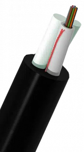 Multicom’s G.652D Aerial Self-Supported ASU Fiber Optic Cable has a loose tube structure and water-resistant gel compound to provide crucial protection for the fiber. This Zero Water Peak fiber optic cable offers up to 12 percent more reach and 27 percent greater served area than the leading LWP competitor. ZWP fiber’s lower inherent loss allows higher network design margins, and thus can support more connections and splices than LWP fiber.
For all FTTx applications including campuses and metro applications, ETC’s ZWP fiber can reach more customers, provide greater network design flexibility, and can generate more revenue than LWP fiber – significantly increasing return on investment in network infrastructure.
Fiber Specification Comparison:
| Fiber Type | G.652.A | G.652.B | G.652.C | G.652.D |
| Wavelength Range | 1310-1550nm | 1310-1625nm | 1310-1625nm | 1310-1625nm |
| Maximum Attenuation Coefficient |
1310nm: 0.5dB/km 1550nm: 0.4dB/km |
1310nm: 0.5dB/km 1550nm: 0.35dB/km 1625nm: 0.4dB/km |
1310-1625nm: 0.4dB/km 1382 ±3nm: 0.4dB/km 1550nm: 0.3dB/km |
1310-1625nm: 0.4dB/km 1382 ±3nm: 0.4dB/km 1530-1565nm: 0.3dB/km |
| Application | 10G, 40G, 10 up to 40km | Higher bit rate applications 10G | Similar to G.652.A Transmission bands can extend to E, S & L. Suitable for CWDM systems |
Similar to G.652.B Transmission bands can extend to E & S. Suitable for CWDM systems |
Bands (wavelengths) – See the graph above
 Fiber Enclosures, Fiber Optic Patch & Splice Enclosures are called many different names: Termination Panels, Patch & Splice Panels, Fiber Splice Box, Splice Distribution, Fiber Splice Panel, Patch Panel, Fiber Optic Panel, Patch & Splice Panel, Patch & Splice Module, Fiber Splice Closure, Fiber Splice Chassis.
No matter what you call them, they all describe a box that contains the devices to connect various fiber optic cables.
Fiber Enclosures come in different configurations such as rack mount (FIG. 1A), wall mount (FIG. 1B), and indoor or outdoor.
The rack mount type is made for 19 inch rack mounting. They may be one or more rack units (RU) high depending on the number of connections required.
One type uses fixed front panels (FIG. 2), (usually 12 slots), for mounting the appropriate adapters. Another incorporates 3 removable front panels (FIG. 3), that can accommodate 6 to 12 simplex or duplex adapter panels each. See an example of this type of Fiber Optic Patch and Splice Enclosure, here.
The rack mount enclosures come in two flavors. One is the slide-out variety (FIG. 4), and the other incorporates a removable lid (FIG. 5). The slide out type is more expensive while the lid type is less expensive but requires the user to remove the whole enclosure from the rack to gain internal access.
The indoor wall mount is available in two or four panel construction. Outdoor Patch & Splice enclosures are used on pedestal or pole applications.
Another ingredient is the splice tray (FIG. 6), that is used for efficient management and storage of the spliced fiber optic cables.
Fiber Optic Adapters are installed into the cut outs in the enclosure to accept the various fiber optic connectors. Fiber optic pigtails (a fiber optic cable with a connector on one end), mate with the adapters and the fusion-spliced tails are stored on the splice tray.
Fiber optic jumpers and pigtails can be either Single Mode (SM) yellow or Multimode (MM) Orange.
| Connector | Types | Color | Application | Configuration |
| SC/APC | Angle Polish | Green | Video, Data, Voice | Simplex or Duplex – Larger than LC – Lock on |
| SC/UPC | Ultra Polish | Blue | Data, Voice | Simplex or Duplex |
| LC/APC | Angle Polish | Varies | Video, Data, Voice | Simplex or Duplex – Smaller than SC- Latch |
| ST/UPC | Ultra Polish | Varies | Data, Voice | Simplex or Duplex |
Common Connectors Names:
SC = Standard Connector, Subscriber Connector, Square Connector
LC = Little Connector, Lucent Connector, Local Connector
ST = Straight Tip Connector
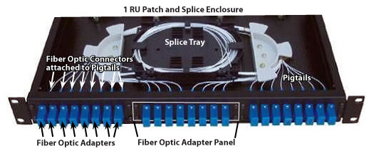
By Ron Hranac, Senior Technology Editor
Ours is a world of numbers, and in cable we tend to use a lot of really big and really small numbers. Fortunately, there are several ways to simplify how we describe those numbers, which I’ll get to shortly.
In reality, it’s hard to grasp just how big or small numbers can be. Consider the number 1,000,000. When discussing an RF signal, 1,000,000 might be the signal’s frequency, as in 1,000,000 Hertz (Hz). It also might represent data rate – say, 1,000,000 bits per second. But just how big is 1,000,000?
If you were to count to 1,000,000, how long would it take? If we assume the average person needs second per number, and you count nonstop (no sleeping, eating, drinking, or …) to 1,000,000, it will take a million seconds. That’s just over 11-1/2 days. From that perspective, a million is a pretty big number. It’s generally inconvenient to deal with large numbers like that, which is where the International System of Units (SI) – specifically SI prefixes (http://physics.nist.gov/cuu/Units/prefixes.html) – can help. Our 1,000,000 Hz frequency becomes 1 megahertz (MHz), and 1,000,000 bits per second is 1 megabit per second (Mbps).
Have you ever wondered why we use the decibel to express signal levels? Why not just use the signal’s actual voltage or power? One reason is the very small numbers that make up typical cable network signal levels. Think about the minimum per-channel input to a subscriber terminal, as defined in Part 76 of the FCC’s Rules: 1 millivolt (75 ohms), or 0.001 volt. 0.001 volt isn’t too cumbersome as far as the number of zeros to the right of the decimal point, but how about the same signal level expressed as power, or 0.00000001333 watt (13.33 nanowatts)? A line extender’s typical perchannel input level is 0.010 volt (10 millivolts) or 0.000001333 watt (1.33 microwatt), and its per-channel output is 0.251189 volt (251.189 mV), or 0.000841276 watt (841.276 µW). Can you imagine dealing with numbers like these on a daily basis? The decibel allows us to express these same levels as 0 dBmV, +20 dBmV and +48 dBmV respectively, using the formula dBmV = 20log (signal level in mV/1mV). Nice mathematical shorthand!Have you ever wondered why we use the decibel to express signal levels?
One measure that we deal with, often indirectly, is the speed of light. In a vacuum, light or any electromagnetic signal, for that matter zips along at 299,792,458 meters per second, or 186,282.397 miles per second. That’s really, really fast. How fast? Let’s imagine a beam of light that could somehow travel unimpeded around the Earth’s equator. For this example, I’m ignoring terrain obstructions, reflection, atmospheric refraction, the atmosphere’s slightly different velocity of propagation compared to a vacuum, and the fact that light prefers to travel in a straight line. In one second, that beam of light will go around the Earth nearly 7-1/2 times!
How far will light travel in the blink of an eye? Normal eyeblink duration is typically 150 to 200 milliseconds (ms), so for this example let’s call it 175 ms. In a blink of an eye, then, our light beam will have traversed 32,599 miles, or roughly one-and-a-third trips around Earth’s equator. In case you were wondering, Earth’s equatorial circumference is about 24,900 miles, or 256,948,534 dollar bills laid end to end.
How long does it take for RF signals to travel through 1 foot of hardline feeder coax? Assume the cable’s velocity of propagation is 87 percent, which means that RF signals travel through the coax at 87 percent of the free space (vacuum) value of the speed of light. Eighty-seven percent of 186,282.397 miles per second is 162,065.685 miles per second still really fast! It takes a mere 0.00000000117 second (1.17 nanosecond) for RF to travel through a foot of coax. A nanosecond is a billionth of a second!
While I’m on the subject of light, how far does light travel through space in one year? The answer is about 5.879 trillion miles, which we call a light year. No, a light year isn’t a measure of time; it’s a measure of distance. A really long distance. Do you remember NASA’s Voyager 1 and 2 spacecraft from the late 1970s? They’re headed out of our solar system at about 40,000 miles per hour. At that speed, it will take 16,766 years to travel one light year. If the Voyagers were headed directly to the nearest star beyond our solar system – Proxima Centauri, just 4.22 light years away – it would take them 70,752 years to get there. Where is warp drive when we need it?
OK, let’s get back down to Earth. The cable industry has been using singlemode optical fiber in HFC network architectures since the late 1980s. A common optical wavelength for transporting signals from headend to node is 1,310 nanometers (nm). 1 nm is 0.000000001 meter, or a billionth of a meter – another really small number. The light inside the fiber is an electromagnetic signal, not unlike the RF inside of our coaxial cables. Well, except for the fact that it’s a lot higher in frequency. How high? How about 228,849,204 MHz? That’s a lot of megahertz, so we can whittle it down with the SI prefix tera ( terahertz or THz ), which makes our number 228.85 THz . Light at 1,550 nm has a frequency of 193.41 THz.
Going the other way, why not refer to RF signals in our cable networks by Wavelength rather than frequency? 5 MHz is 59.96 meters, 42 MHz is 7.14 meters. 50 MHz is 6 meters, and 860 MHz is 0.35 meters. In the old days, radio signals were expressed in terms of wavelength. Ham radio operators still use wavelength to describe the spectrum allocation for two-way communications: The 80 meter ham band is 3.5-4.0 MHz, 40 meters is 7.0-7.3 MHz, and so on.
Before I get too far away from singlemode optical fiber, here’s an interesting tidbit. The diameter of the fiber’s core through which most of the light travels is about 0.0000083 meter (8.3 µm), or 8.3 microns. That’s roughly the same size as the Giardia protozoa, a nasty little germ familiar to backpackers that can cause great tummy discomfort if, say, one drinks unfiltered or untreated water from some mountain streams.
SI prefixes and the decibel are two mathematical shorthand methods we use to deal with very large and very small numbers. Another mathematical shorthand for large and small numbers is scientific notation. The latter is commonly used for bit error rate (BER) sometimes called bit error ratio which, by definition is the ratio of errored bits received to the total number of bits transmitted. For example, if we transmit 1,000,000 bits, and three bits are received in error at the receiver, the BER is 3/1,000,000 = 0.000003. In scientific notation, this BER is 3 x 10⁻⁶, or 3.00E-6.
Scientific notation can be confusing if you’re not careful. Which of the following is a higher (worse) BER: 1.00E-6 or 1.00E-9? This one’s not too difficult: 1.00E-06 is 0.000001, and 1.00E-9 is 0.000000001, so 1.00E-6 is the worse of the two because there are more errors. How about 1.00E-6 and 3.72E-6? Here we’re comparing 0.000001 and 0.00000372, or 1 errored bit out of a million bits transmitted vs. 3.72 errored bits out of a million bits transmitted. So 1.00E-6 is a better (lower) BER than 3.72E-6.
Let me leave you with this question: What are the biggest and smallest numbers you deal with regularly?
Ron Hranac is a technical leader, Broadband Network Engineer, for Cisco Systems and senior technology editor for Communications Technology. Reach him at rhranac@aol.com. Originally appeared in the June 2007 issue of Communications Technology magazine. Reprinted with permission of the author.

Multicom provides a large variety of Webinars for Cable Operators from Commercial Satellite Solutions to Pro:Idiom® Hospitality Solutions
https://www.youtube.com/watch?v=Ep1BYN3h8vA
https://www.youtube.com/watch?v=hJXzeBstJys
https://www.youtube.com/watch?v=Me1I7uN5dIY
https://www.youtube.com/watch?v=KOUT4NOiMDo
https://www.youtube.com/watch?v=E375SiJ3msE